This week on the BBC series: the inlay desk, a special system for generating keys and other special effects for use during programs.
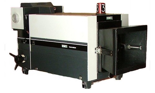
The inlay desk was basically a camera aiming down at a backlit desk. But it does appear to have more controls than just being a camera. Unless of course, those controls to the left side of the operator are just a form of CCU. Apparently, as the studios were colorized they were upgraded accordingly to have multiple layers of video color separation. Can't image how that would look or work, but sounds pretty awesome. In this particular picture it's neat to note that the camera looks almost exactly like the camera in the NODDY array. This is probably not too much of a surprise because the NODDY array was basically a generator of keyed graphics (at least when color came around).
Not too much out there on this piece of equipment. Most of the info I have comes from TV Studio Histories again. I can't find too many mentions of it in engineering documents, but it also took me a while to learn that EP5/512 meant "that video mixer with the faders."
If one were to piece some things together from the aforementioned website, there is discussion about the formulation of a video effects studio. Until it was built, video effects were done in the galleries of TV studios that were undergoing a set change and therefore idle. This was most likely one of the pieces of equipment they used to generate the various effects, as every studio gallery had one. There is however, no mention of the device being installed in the new video effects studio, but by that time, the 80s, I would assume it was probably thought obsolete.
This device does kind of remind me of another device developed in America, although with greater and different capabilities, called scanimate. Scanimate had an input device that was similar to this setup, but could do more, in the sense that it could alter the scan rate of its camera. This ability had the effect of making things "roll" as the image produced by the camera was re-photographed with a standard camera. Essentially it took advantage of the effect that occurs when you try to film a CRT screen. There was way more to it, but we were trying to stick to the BBC weren't we?
On a personal project note, I have been playing around with transistors (still) and am working on several guitar pedal-like devices as well as germanium input amplifiers for microphones. In addition, also bringing an ADAT digital tape recorder back to life. Perhaps another week.
To leave you today, I found a cool video montage about Television Centre that has become one of my favorites. Enjoy
Wednesday, October 9, 2013
Wednesday, October 2, 2013
The BBC EP5/512 Vision Mixer
This week we take a look at one of the most unique video switchers that I have ever seen, the BBC EP5/512 vision mixer:
However, to call it a video switcher is misleading. It does more than your average video switcher, and that is why it is referred to as a "mixer." Just looking at it can tell you why that is. This "mixer" has the unique quality of being able to switch or mix up to 8 sources at one time. Rather, it has two modes- switching and mixing. Like any 8-source switcher, there are two banks of inputs, with switches to select what is present on that bus. The two banks can then be switched or wiped based on a special effects panel. Pretty standard for a switcher. The only neat thing in this section is that there are pluggable units for the effects section that expand the available wipe effects up to 106. Still, pretty standard.
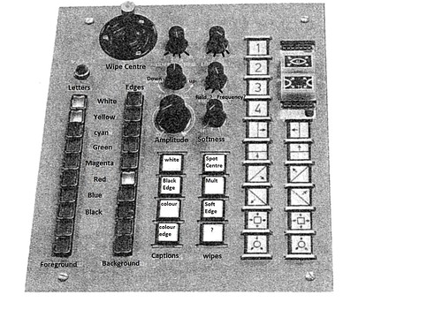
The effects panel of the ep5/512, showing pluggable wipe units in upper right corner
The special features of this mixer appear when you start asking what the faders are above the selection switches. These actually form an additive mixing section for each bank. When the mixer is in switching mode the faders are inactive. However, when a fader is topped (brought to its highest position), the selection switch pops out and the bank is now controlled by the mixer section. Theoretically all eight channels could be combined in the image on the screen. The mixer has limiting circuitry built in to prevent the image from deviating from standard transmission line voltages. With this ability, very complex layered images can be created. Certainly with modern cascaded switchers, complex overlays can be done, but it would require multiple buses and effects bars sitting in their (I feel, unstable) middle position. Also, with a setup that takes up the same room as a single bus 16 input switcher.
To switch back to switching mode, press a selection switch and control is returned to those selectors. It's here where I get a little confused, because the fader can remain topped and selection can be changed over to the switches. It would be my guess that you would have to lower and top the fader again in order to regain control with the mixer. I have yet to find an operational manual for one of these mixers. All of the information that I have for this comes from an engineering manual and a (of all things) clip from a Blue Peter episode. The engineering manual was found on bbceng.info which is a marvelous site for learning about all of the tech that the BBC employed on a very small scale (I mean down to the individual modules that make up consoles and apparatus). Unfortunately, no instruction manuals...
The Blue peter episode, reproduced below, gives a neat look into the gallery (or control room if you prefer) of TC1. It's a neat little clip, but for just the mixer, skip to the 5 minute mark.
According to the manual, the switcher also had the ability to put black borders around white captions or to synthesize alternate colors on them. Also, the ability to remove color for keying. In the Blue Peter video, you can just barely make out "overlay" and "background" on the two rows of pushbutton switches above the faders. Most of the labels on these diagrams from the manual are illegible due to the angle they were taken from and the black and white scan of the manual. To get the images look better and to be able to read the labels, I blurred the images a bit. These are the images you see here. I had to toggle between the two to trick my eyes into seeing the labels. This is what I was able to make out from the effects panel (click for a larger image:
It seems that the rows of knobs go in line with the rows of switches, so despite not being able to see their labels, I figure the knob above amplitude is a positioning knob for the captions and then some other knob that seems labelled 1,2,4 and 8). Softness is a switch I figure- "four degrees of hardness" the manual states. The rest, I have not much of a clue. The top right seems to start with "limit" but I doubt that its the control for the mixer's limiter. It's really interesting to figure though, that the mixer has such comprehensive controls for something kind of almost trivial- caption coloring. The wipes are quite neat though, and this view gives a great view of the pluggable modules. There are none installed on the Blue Peter program. Oddly enough, in this diagram, the color selected is light yellow text with a red edge.
UK TV studio History has some neat stories about this mixer, but not too much. As a matter of fact, there's not much out there at all for this mixer. It's weird though, because it was a very long lasting mixer, surviving from the dawn of color almost to the end of the EMI 2001 (although was most likely phased out sooner in the mid 80s)
Wednesday, September 25, 2013
A Break From the Beeb
Taking a quick break from obscure BBC equipment because, well, it's a lot to write up and I've been 'busy.' I have however been playing around with transistors and the idea of building preamps and/or effects boxes. I recently bought a small cache of germanium transistors to play around with (Toshiba M8640E) and want to use them for something. So far I have gotten into the idea of making a fuzz pedal and have been researching those. I also had a little fun playing around with a 2n5089 that I had kicking around-just experimenting with bias levels and overdrive, using a tube sine wave generator to drive it and looking at the output on an oscilloscope.
It's really been a period of maintenance here. I'm working on getting the sine wave generator re-capped and did a modification to a Mackie mixer I have that has been a bit troublesome. More on this later.
So as to not leave you with nothing about the Beeb's equipment, the next obscure piece of BBC equipment I'll be talking about is the very unique "vision mixer" that the BBC used for an extraordinary amount of time (probably early 1960s into the 90s).
This rather neat photo shows the mixer in its natural habitat (the center thing that kind of looks like a sound console)
Photo from TV Studio History
Wednesday, September 18, 2013
The NODDY Camera
Continuing with the theme of interesting custom BBC equipment, this week I am going to talk about the NODDY camera.
The NODDY camera was a specially-mounted camera in a room of the BBC used only for the purposes of generating 'slates' for out-of-vision continuity.
For someone outside of Brittan, continuity was quite foreign to me. But the concept of making announcements between programs, introducing the next is quite neat. Most of the function of continuity is now provided, although much more limited, by lower-third graphics in the States.
The NODDY camera was what generated the globe in the video. The globe is actually a mechanical model in an array of other models and cards saying various things; clocks, globes, station identification and apology messages. A black and white camera would remotely "nod" and turn to position itself to display the appropriate image. It could then be taken live on air to introduce a program or substitute when said program went off the air unexpectedly.
It seems like such an immensely simple thing. Most of the time studios would use slides in slide scanners, or prepared cards to do graphics. The BBC, with a need for quick repeatability, decided that it needed a custom automated device to produce graphics for their continuity announcements.
The cards that these NODDY systems used were just cardboard with graphics on them but the more interesting "special effects" were the clocks and globes. The Globe was a particularly interesting special effect. It was an internally lit ball coated with translucent black paint to denote oceans. A wide, curved mirror then stretched out the globe's reflection to give the globe's background. When the BBC started using color, they would synthesize the color using the signal from the black and white camera. This wonderful little video describes how it was done as well as showing a bit of how the globe model looks.
There are only a few websites that talk about the NODDY camera. There are even more that talk about the models that were used in them, but there really isn't much information about what could be called "the most seen studio at the BBC." I'll finish with a few pictures of the models used in the NODDY system.
A good view of some of the slates and globes
a view of a globe showing the curved mirror a bit better.
A BBC clock from the NODDY array
Wednesday, September 11, 2013
The EMI 2001 Color 4 Tube Camera
For a very long time now I have been interested in, if not amazed by, some facets of the BBC. Specifically, the equipment used during the formative years at Television Centre. Even moreso with the oftentimes custom-built devices that they used to produce their programs. Much of the equipment that was used in the period from the early sixties to the mid 80s was not used anywhere else. I'm going to do a series of posts working out much of the information that I have collected over the years of how this equipment was used and operated.
Most of the information that I have here comes from a most marvelous website, TV Studio History that I had lost for a while and recently stumbled upon again. It's a great and well updated account of many of the UK's television studios, including the myriad equipment at Television Centre.
This week we'll be looking at one of the absolute workhorses of the BBC and a favorite camera of mine, The EMI 2001.
Photo from TV Camera Museum
The EMI 2001 was quite special in the sense that it actually lived for a very long time. The last of its kind was finally retired in the early 90s, probably when they could no longer keep them alive off of spare parts. Not bad for a camera made in the mid 60s. The story seems to go that they were kept around because they were extremely good at reproducing pictures. Despite using plumbicon tubes, their pictures seem much sharper than say the American equivalent the Norelco PC-70, if you could really call it that. What was so special about the way that the 2001 produced its color picture was that it used 4 tubes instead of three, like most other color cameras. The fourth tube was used as a luminance tube, generating the black and white signal that would be added to the color (chrominance) signal generated by the other three tubes. I'll discuss how this works in a little bit.
The last 2001s to be used by the BBC at Elstree studios on the day of their retirement in the early 90s. Photo from wikipedia.
The way that the BBC happened to order these cameras is quite an interesting story. The BBC had been doing color tests for years trying to figure out a system that would be compatible with the existing black and white standard. There is a great video of this on youtube that gives a (staged) look into these tests as early as 1960. These first cameras were based on the RCA TK-41 and were manufactured by Marconi. By the time the BBC had decided they were ready, around 1966, EMI and Marconi had developed color vidicon cameras that were being considered. EMI had produced the 2000 and Marconi the MK VII. Disappointed with the quality EMI offered, the engineer bought around 7 Marconis to outfit the first color studios, TC6 and TC8.
For a minute I'll talk about the Marconi. The Marconi MK VII was a behemoth of a camera. It was super long and the body of the camera was large and heavy. Any pedestal that these were mounted on required a larger ring to steer it with. In addition, the lens used was made for an Orthicon camera that had a much larger sensor (probably about 3 inches) that when used with the much smaller vidicon sensors had the effect of reducing the area picked up and "lengthening" the focal length of the lens. The result was large, long, heavy cameras that had to be long distances away from their subjects to get the shots they needed.
A Marconi MK VII. Operator provides a reference for scale. Photo from Tech-Ops History
In this time, EMI went back and revised the design. They replaced the vidicon tubes with Plumbicons (lead-oxide based vidicons) and made some other tweaks. The engineer, realizing his mistake, bought the new EMI cameras, now designated 2001, and soon all of Television Centre was outfitted with EMI 2001s. The leftover Marconis were moved into the presentation and news studios, camera movement being less of an issue in those programs. Oddly enough, the presentation studios are where Old Grey Whistle Test originated from, which must have been difficult with a small studio and large cameras.
The way that the EMI camera overcame the difficulty of the large amount of circuitry needed to operate the camera was twofold. First, most of the controls were moved to the Camera Control Unit (CCU) requiring quite a heavy 101-core cable to connect the two. Second, the remaining circuitry was wrapped around the lens of the camera. The little bump at the front of the camera is just a lens hood. The lens is completely internal to the camera. This decision made tilting the camera much more intuitive and balanced, but limited the types of lenses that could be used with it.
Exposed sides of the 2001. Top photo shows large camera cable in center bottom. Photo from Radio and Electronic Engineer 1970
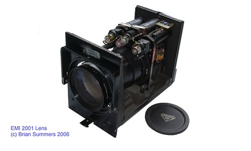
An exposed EMI 2001 lens, showing servos. Photo from TV Camera Museum
The lens itself was also quite interesting. There were provisions so that the entire camera could be remote controlled, therefore the lens is controlled entirely by servos. This aspect allowed the camera to be very operator friendly. A panel on the back allowed the operator to set zoom presets. It was speculated that these were made to emulate the older style turret system, so different focal lengths could be programmed in and switched to with the press of a button. Too often I have wanted a control like this on modern cameras... Focusing was done with the three-spoked knob on the right hand side of the camera, reminiscent of the focus controls of the older cameras.
But. How does it look?
Actually, quite amazing. There's a reason these cameras stuck around for so long. When in a well lit studio they had quite good color reproduction and very good black levels. They got noisy in low light situations though. Only every so often was there an issue with image lag. The EMIs did not have any form of ACT (anti-comet tail) circuitry so whenever a glimmer of something bright was caught, it did blur across the screen, oftentimes in a multicolor spread. Machines that were kept late into their lives were often upgraded to add such circuitry but a good number of parts needed to be changed in order to do it.
To find good copies of many programs on the internet that were filmed with EMI 2001s is somewhat hard. Most of it was recorded onto Quadruplex tape, known for its quality, but has often been transferred onto other and inferior tape formats (or compressed to death digitally). Some of the best looking footage not from a sit-com is actually a program made in 1969 called "Pop Go the Sixties," a retrospective of 60s music produced by the BBC and ZDF, a German television company. This clip of Lulu on the program demonstrates its quality quite well.
Keep an eye out for stray lens hoods and cross-shots! (this program was kind of littered with that...)
The reason the camera is so sharp is due to its unusual design. Most cameras being made at the time (and to this day) were made with three sensors- red, green and blue. The signals from these are then combined to create the luminance and chrominance signals that make up the compatible color system. The EMI however, uses a fourth tube to create the luminance channel. The only other place I have seen four tubes used in this fashion was in RCA telecine cameras (The RCA TK-42 and 43 used a similar technique, but they used an orthicon tube for lum. and vidicon tubes for the color signal). The design makes the camera heavier, but offers more versatility with the tubes regarding color accuracy, sharpness and deficiencies with the tubes.
I have a document released in Radio and Electronic Engineer in 1970 that details the operation of the 2001. It gives a comprehensive description of the background, optics, electronics and mechanics of the 2001. The most interesting, or perhaps mystifying, part that it describes is how the colorimetry of the four tubes is performed. Like a standard camera, the 2001 creates a luminance signal by blending the color tubes together. But instead of blending this signal directly with the red and blue signals to make the chrominance signals, it creates a difference signal with the bandwidth restricted signal from the luminance tube, then blends that difference signal with the full-bandwidth luminance signal. This is shown diagrammatically in the pictures below, first the three tube, and then EMI 4 tube version.
The standard method for deriving the luminance and Chrominance signals from a camera.
Signal generation in the EMI 2001 utilizing four tubes and "Delta L" luminance correction.
EMI's reasoning for this style of signal generation was due their belief that the luminance signal that is generated from the luminance tube is different from the signal generated from the blending of the color tubes, especially when the camera is aimed at saturated colors. This "delta L" signal could be used for a number of purposes, one in particular being to correct for color insensitivity in the luminance tube. The tube could be bolstered to produce greater luminance in, say, the red spectrum if it needed it. All the while, the luminance signal would still have the advantage of the crispness afforded to having a separate tube. It is most likely that the Marconi MK VII (which was also 4-tube) used the luminance tube directly, without accommodating for this error, and many people did not like the color color tones it produced as a result, specifically flesh tones.
To end this piece I will leave you with a video demonstrating the operations of the EMI 2001. There are plenty of other videos out there featuring this camera, but this two-part video provides a really good look at all the features of the EMI.
Sunday, September 8, 2013
Coming Plans
I've realized that if I don't define a specific date to update things by, I'm not going to update. Therefore, I am establishing Wednesday updates! Every Wednesday I should have some musings about tech and general trouble that I get myself into (mostly involving tech).
Despite this blog's appearance, I have been working on some projects, and want to talk about a few neat things. Specifically, rebuilding a tape recorder, playing around with transistors and tubes and working on some recording equipment. I've also been doing some research about old BBC equipment on the belated occasion of Television Centre's demise. In particular, their old vision mixers and the EMI 2001 color camera.
So keep your eyes peeled for an update this Wednesday!
Tuesday, June 25, 2013
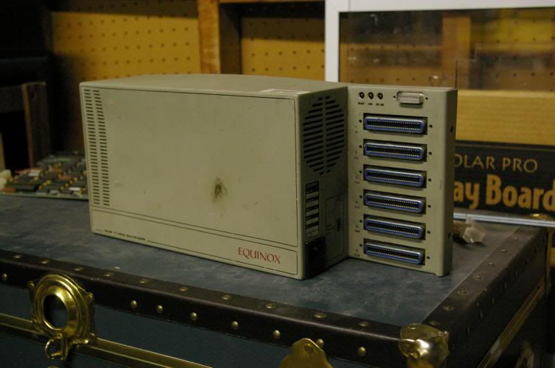
An Equinox LM-48
So I got hit with a bout of appendicitis, so I apologize or not posting, but as promised I am going to talk about the digital telephone multiplexer that I have. Here goes:
A couple years ago I found this quite battered piece of phone equipment being thrown out along with a number of other boards.
It looked interesting and claimed to be a T-1 multiplexer so I brought it home and started doing some research. As is the case with most of the things I find, there was little to nothing. But I'm also not one to give up on something without a story. It wasn't until I unearthed it just recently that I searched again and found it mentioned in some old telecom magazines that Google has now digitized.
Long story short, it is a part of a digital telephone system. It multiplexes 48 telephone lines for interface to a private branch exchange (PBX). Equinox was a manufacturer of PBX, specifically digital ones for companies. This device would have been used to interface up to 48 RS-232 lines to a single T-1 line that could then be switched and processed.
...and that's about all I've got. The articles that mentioned the device were mostly talking about the viability of Equinox to provide faster data rates for modems through the device, specifically 9600 kbps (it was the late 80s). So the specific way in which it works and the pinout of the 50 pin connectors on the side are kind of lost. Although what use is an old device like this other than parts and history?
What does befuddle me is the fact that it claims that it is a T-1 multiplexer. A T-1 line by definition is supposed to only support 24 phone lines. In order to handle twice the amount of lines the system would need to either double the data rate of the transmission line or limit the number or precision of the samples.
I've come to the conclusion that it's not a T-1 line by definition. It's probably some proprietary standard that equinox used that may be similar, but adjusted to handle only digital data. I'll never stop researching though....
So now with some more information about the device there is only one more thing left to do- crack it open.
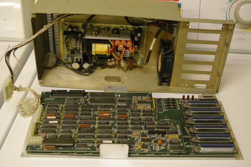
When I found the machine it was covered on the inside with a fine black powder that had been sucked into it by the internal fan. I just ran it under a stream of water to clear it off. This shouldn't have too ill an effect on it. But, upon first glimpse there are clearly three main components- a power supply, a control board and a data board(called a driver board).
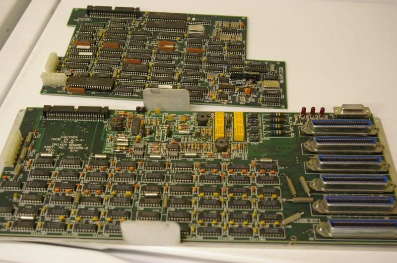
Close inspection of the control board shows that it's a standard micro-controller system with a bunch of 7400 series chips to make it talk to the other circuitry. It's connected to the driver board by a ribbon cable.
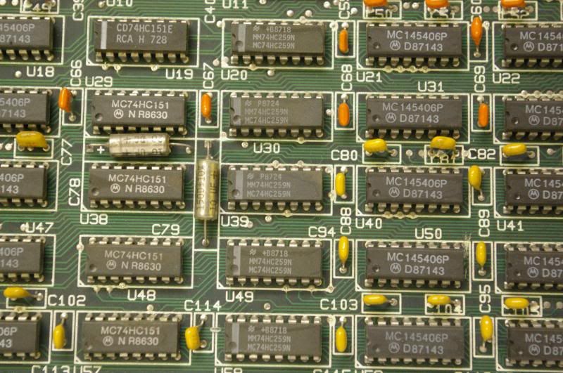
The driver board is much more interesting. I originally thought that this was for an analog phone system and it wasn't until studying the chips on this board that I realized it was all digital. The bottom half of the board, with the array of chips, contains only three types of chips. First, an RS-232 driver, which tipped me off to it being for digital phones, then pairs of 1-to-8 and 8-to-1 digital multiplexers to drive and sample the serial RS-232 lines, respectively.
The top portion of the board is all the circuitry to handle the transmission line to the PBX and contains what look like a couple of hybrid networks and line drivers.
As would be assumed, the device is pretty purpose-built. Looking at the circuitry the microprocessor just cycles through the RS-232 inputs, sampling, possibly storing and then transmitting their contents down the "T-1 line." Also, simultaneously reading the "T-1 line" and distributing its data to the RS-232 lines.
Kinda boring.
I would say it could be used to fan out a computer's serial access for terminals, but it would really require a lot of work on the processor's part. Alternatively if it had used UARTs it would be more interesting, but for a phone system board that would be a bit overkill.
Despite it being rare, and because it's not too interesting, I might just scrap this for its RS-232 drivers and other chips. In an attempt to see if the power supply was salvageable I found out why the thing was trashed in the first place. The -12v rail of the power supply was only putting out -10v. So there may be some hope yet for these parts to live on.
Friday, June 14, 2013
The Origins of VOIP
The other day someone asked me how VOIP (voice over internet protocol) worked and it got me thinking about the origins of digital telephony. I have a mild (hah) interest in telephony, loving every automatic switching system Ma Bell ever made. Too many days have been spent scouring the internet for descriptions of SxS, panel, crossbar and ESS switches. One of the things that has also piqued my interests was the various trunk lines that the Bell System used to carry long distance calls, including the very beautiful WECo microwave "funnels." Developments in both of these areas, first trunks then switches, will combine to form the basis for the digital subscriber line that many of us use in our homes and offices.
Our story starts perhaps a bit earlier than you might expect it to, back in the 1960s. In the Wikipedia article for VOIP the earliest recorded event in VOIP history is the development of a "Network Voice Protocol (NVP) developed by Danny Cohen and others to carry real time voice over Arpanet" in 1973. But we had the inklings of digital telephony as early as 1961 when Bell Labs introduced the T-Carrier, commonly known as a T-1 line. T-1 was a trunk multiplexer. It could carry 24 phone calls -digitally- over a pair of copper cables.
Before the introduction of T-1 the only way to carry multiple conversations over a single cable was to treat them almost like radio stations using an L carrier. Each conversation would be filtered and then modulated with a certain carrier to have it fit into a certain bandwidth. For example, you could take four signals, low-pass filter them to 4KHz and modulate them with frequencies that put them in different bands of the transmission line such as 20K, 25K, 30K and 35K (allowing for a little guard band). Then you could apply a similar process and get 16 lines down one pipe in full analog. But this was the 50s and these things were expensive, so pulse code modulation was considered as an alternative. In addition, the call quality improved, so they were all the more better for it.
So now we have all these digital trunk lines going everywhere, but the odd thing is that every time one of them passed through a class 4 switch (those that handle long distance linking) the trunk line was decoded back to analog, switched and then perhaps re-encoded to be sent off to a local office. This odd little practice caused a controversial change to be made in the way in which long distance calls were routed. In 1970 Bell began to develop the #4ESS, a completely digital class 4 Electronic Switching System. T-1 lines would come in, their data would we parsed and then routed through T-1 lines going out. Calls could now be completed long distance as if you were still calling within your own district (at least quality-wise). The first #4ESS was delivered in 1976 in Naperville, Illinois.
Now that we've gotten into the seventies, we need to take a step back to the sixties to start looking at the development of the internet. The idea first started as a government project, in the 1950s as the SAGE air defense network and developed into commercial and private computers being able to use standard phone lines and leased lines to send data to each other. Originally it was just a number of "dumb terminals" dialing in as users on a shared system or universities sharing programs by sending them serially (perhaps simply even tape-to-tape over a phone line). But towards the end of the decade, plagued by bad connections and the desire to have a constant network of shared information, a protocol was developed of sending packets of data so that if any one of them was somehow corrupted, the receiving computer could ask for that one little bit to be re-sent. Soon the military would get involved again and the rest is the history of the ARPANET.
Here's where we catch up with the developments made in 1973, because those individuals took the first development, pulse code modulation, and paired it with the new network that was starting to parallel the phone system. However, it appears that these were simply "voice" over the internet. As much as you could send someone an email or share a program or data, you could communicate with someone over this new internet protocol. However, you could only do that with someone who had access and the proper equipment and was online. You could not really call into the standard phone system. This was essentially a single phone channel out of the T-1 line using the internet as 'wires.' This is where the #4ESS comes back into play.
At the time the #4ESS was developed, the reason the developers decided to do switching completely digitally wasn't entirely because they saw the demodulation-remodulation as silly, but also because they saw the writing on the wall and realized that digital switching was the future. When you encoded things digitally and then sent them down a wire you could do so many things so much better than a standard analog switch. When higher level of T-carriers came out, the data that was coming in on slower T-1 lines from local offices could then be routed to faster T-2 or T-3 lines that could carry many more calls in between long distance offices. It was no longer a one-to-one relationship in transmission speed, which is kind of similar to the packet system, where bits could be sent anywhere in little chunks, or frames, to use T-carrier language.
As much as it was a similarity to packets, it was kind of a downside of T-1 that it was just a 24-channel transmission line. You could only send data down it in a specific way, in frames of bits that designated channels. But, theoretically once you got rid of the multiplexer and used it to interconnect class4 offices, it was just a 1.544Mbit/s data channel. You could send anything down it. Eventually this is what happened and some of these connections were used to form the backbone of the internet.
As a bit of an aside, I feel many people think that the internet was carried on phone lines originally because they used to use modems to dial into it. But I don't think that many people realize that the internet, up until somewhat recently, was completely separate. When you 'dialed in' to the internet, you were dialing into a serial data connection on a computer (similar to what we did in the 60s with terminals) that was connected to the internet- through which you could access data on it. This is part of why the next step almost perhaps seemed seamless when it came out in public use.
It wasn't until the mid 90s that someone realized that they were all using the same data cables to send phone data as computer data and that they already had the technology to send voice through packets and then created what are called "soft switches." Soft switches are essentially class4 and class5 (local office equipment) switches that can utilize the packet system of the internet to carry their voice data. So now for the first time you had a switched telephone network being carried over the internet and ironically carrying calls of people connecting to the internet. But you wouldn't really know if your phone calls were being carried over the internet at this point anyway, so the roundabout-ness of this was not always noticed.
In the present day, with the network of the internet being expanded as it is, where our computers connect to the internet like the computers we used to dial into, the switched aspect of the telephone service can take a completely different shape. Now class4 and 5 switches can be fully implemented as servers run by the phone companies existing as completely integrated bits of the internet. A simple box in your residence can do all of the pulse code modulation of the old T-1 line and send the data as packets out to be processed much like the #4ESS would. Perhaps the transition to this type of system came about in an attempt to not duplicate facilities as the internet was growing. What is clear though is that the idea that we have of encoding everything as data and sending it all down one big pipe to multiple destinations started out as a means of providing a more efficient pipe and a better switch. A phone system is a network. One that carries 'data' that can be encoded. And as demand for internet access grew and more people got better and faster access, enough room for a single 64Kbit/s voice channel was easy enough to provide.
-Always improving. That's the Bell System for ya!-
P.S.- There's one little offshoot in this story. In the mid 80s such a thing as digital telephones became popular in offices. The pulse code modulation was done in the phone and, rather than using an analog line to the switch, were connected via a serial RS-232 line. All switching was still done by a purpose-built private branch exchange, as it had for years prior. However, this is the direct ancestor of phones in offices today that connect via ethernet LAN to access the phone system. These appear to be still and only popular in offices. I have an early multiplexer for one of these systems that I'll be dusting off soon for the cameras - stay tuned!
Labels:
arpanet,
at&t,
bell system,
ESS,
history,
internet,
multiplexer,
phones,
switch,
T-1,
telephone,
trunk lines,
voip
Sunday, June 9, 2013
Terminal velocity
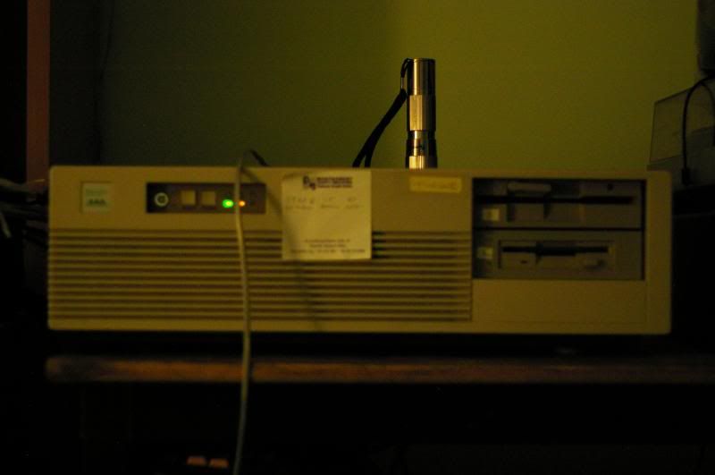
Last night I stayed up way too late playing around with one of the coolest little toys I have: a Microsys 80386 desktop (named 'tongue').
(apparently at 4am flashlights take over your camera and make themselves the focal point of all photos)
Specifically, I was trying to get a dial up modem and terminal emulation software installed on it in order to cruise through some of the last remaining BBSs out there, in true retro style. And well, I hit a wall. That wall is made up of the boxes of old computer bits that I have from the late 80s and into the 90s that have little to no documentation because, well, it was the internet boom and many companies formed, but not all survived. Hence all their documentation which may or may not have existed online is no longer. So when I came across the only non plug-and-play ISA modem I have, of course, nobody knows how it works.
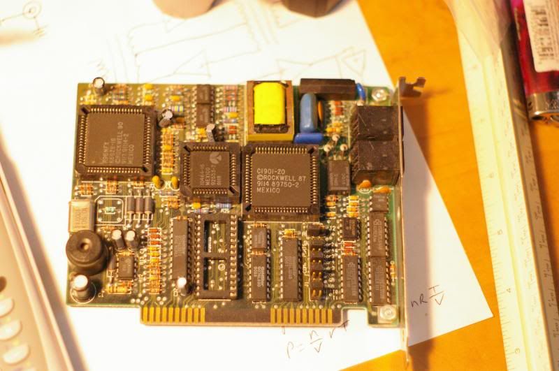
It's a Zoom Faxmodem pc96/24 which means that it has a max speed of 9600bps and slowest of 2400. it's got a bunch of Rockwell chips on it and from other pictures on the net, it also comes with the option of a rom chip in the empty socket lower middle of the card. Past this, I can't get any of the terminal emulators to see it.
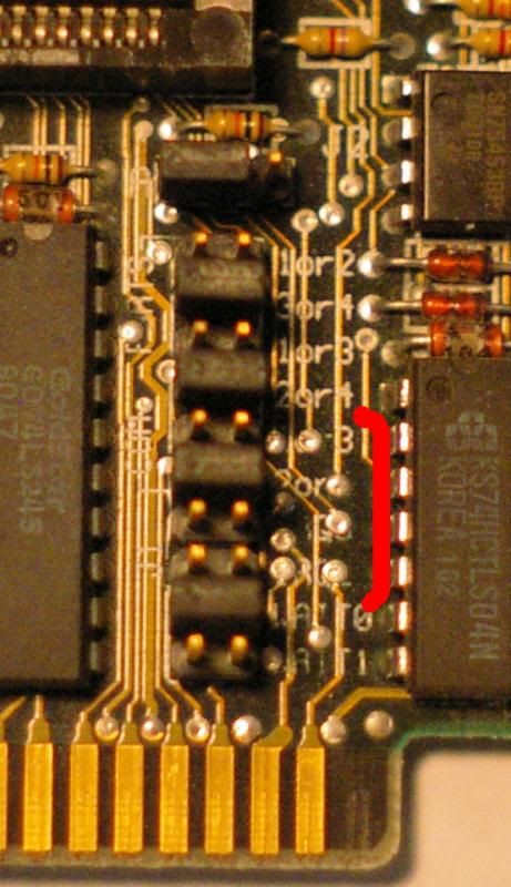
There is some solace however. Some companies were gracious (or cheap) enough to basically provide their manual on the board itself, with well defined jumpers. Keeping this in mind, I took a look at my card and was thrilled and then depressed. The manufacturer (Zoom) had in fact labelled these jumpers, but wouldn't you know it, they weren't great at their placement of text near vias. Once I was able to figure out (just about) how to strap it for which com port you wanted it to be, I tried strapping the IRQ to find the (I've highlighted it) part of the board below.
I could guess at what these say, but... I don't even know if I'm missing a jumper, considering that the pins that I think are for the IRQ don't actually have any on them.
One site that I usually rely on for things like this is stason.org which is a really great resource for when you have no idea what you're holding in your hand, but know the serial number and that it's an ISA card. Unfortunately they don't have my modem in there, or it's one of the unidentified ones that I don't feel like sifting through.
I was able to find some for sale, which would give me a brand new one, with documentation and software probably, but that would mean, like, actually paying money for a 9600bps dial up modem that I already have and I just... I just can't justify that.
I do have another route for playing around with BBSs though. I have a WYSE terminal and an external dial up modem that I have paired. I didn't want to use it with the 386 only because there are open card slots in it and the modem takes up space and a power plug. (I used to do a little party trick with it, using the terminal to tell the modem in Hayes codes to dial a friend's cell phone who would then be amazed that I had called them with a modem.) That setup would probably work with a BBS but I kinda wanted to do more than just view it if I could. I also just wanted to have a modem on my computer that I could use to call it remotely if I wanted to, or setup some kind of BBS of my own. So maybe I'll see if I can find any other options.
(I'll talk a little more about the 386 and the plans I have for it in a later post. It's kind of a lot of dreaming with too many cards and involving other computers and I'll just give that its own post...)
Thursday, May 30, 2013
Memorex Memorabilia
When I was younger and starting to build up my collection of open reel tapes and players I stumbled upon the number of open reel tapes my mom had recorded when she herself was younger. Most of the tapes are pretty standard looking Scotch stuff and some have pretty neat designs on them but one in particular stands out.
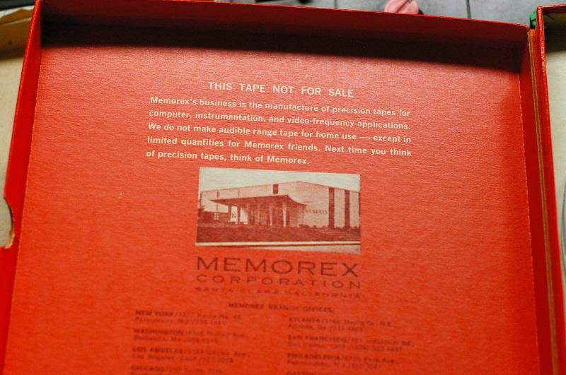
It's quite an attention grabber with its orange jacket and beautiful space-age fonts. But a peek inside the cover reveals that this isn't just an ordinary reel of tape.
The inset reads "This tape not for sale. Memorex's business is the manufacture of precision tapes for computer, instrumentation, and video-frequency applications. We do not make audible range tape for home use - except in limited quantities for memorex friends. Next time you think of precision tapes, think of Memorex."
Looking at the history of the company the tape would have to have been made before 1971 when they entered the consumer market. Looking further at the design of the box it looks similar to reels of their videotape from the mid sixties, so that may be a safe guess. The purpose of this tape was probably to be a promotional tool for Memorex. When this tape was manufactured, the average individual use for magnetic tape was home audio use. By giving these out to people who were distributors or to engineers who showed up at events they could use the tape at home, and be reminded of Memorex every time they did. And why wouldn't you keep it around? Your Possession of it signifies that you're a "friend of Memorex."
At least, that's how I could see an ad executive thinking about it.
Regardless, it is at least an interesting piece of Memorex history, if only for the neat picture of their offices and the cool minimalist design. And if the inset is true, this is perhaps a rare find.
Unfortunately I laced this up a long time ago and well, it's a bit past its prime. There was no original content on the tape and trying to record something on it as a silly high-schooler led to less than desirable results. But then again, at this age its more of a collectors item anyway. And more on the topic of 'collectors item,' there are a few more of these stashed away in better condition than this one and presumably never used either.(So I haven't soiled the only one in existence)
Subscribe to:
Posts (Atom)