Monday, December 12, 2011

Fun With Lighting

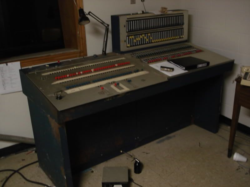
It has been such a long while since I have posted, that I have decided to share with you a story of when I did theatre lighting a few years ago. The facility that I worked at was one that was recently reopened and had not been upgraded since the early seventies. The console (and I do mean "Console") was made by a little known company called Stage-Brite. Stage-Brite wasn't very well known for theatre lighting, but they produced consoles for them none the less. The console we had was a 4 preset, 5 submaster, 30 channel voltage-controlled board. From the original plans and schematics (we had them all), the board looked like it was quite nice (at least for a preset board). However, at some point, the main control panel was replaced with an X/Y preset panel. This move rendered the existing four preset panels completely useless right off the bat.

Ready for a picture of this board?


Photobucket

It was a fun board. Kinda. As pretty much the only lighting designer and one of the few who knew a bit about electronics, the board was kind of my baby. For the two years that I had to operate this board I had to somehow keep it going. It was a challenge. I'll get onto the dimmers themselves in a minute, but the board had some interesting quirks itself.
First, even though the control panel had been replaced, the replacement wasn't in tip shape anymore. It was an X/Y preset board, but only the X preset worked. The Y preset contained many channel faders that no longer worked and if you brought the submaster fader for the Y preset all the way down, the carbon element inside would start to glow. It was much fun switching lighting patterns between scenes, although luckily the dimmers had a lot of power and we were able to keep to only a few of them. What was very interesting about this board was that it got its power from the dimmer itself. The only way to fully turn off the console was to throw a 300 amp breaker in the basement of the facility. Therefore, when working inside the board, there were two open-frame relays that were always hot (that is, the practice was to just hit the console power, which just cut supply to the faders and other control circuitry. Almost all the power supplies in the console remained burning). Long story short, the board was Supposed to have screws to hold the panels down, but they were either lost or never put back in due to the number of times it needed to be opened for maintenance.
At one point, because it was a hazard, I removed the circuitry for the Y Preset submaster. Upon telling the Director of Engineering, I was told that that was not good and that it should be put back so the safety of the board could be demonstrated (we were trying to get a new board). I reluctantly agreed, and after about 15 minutes of time, I had all the cut wires put back. As a check, I flicked the board on and brought up some lights. I then absent mindedly leaned on the top of the board to look at the lights, and they went out. I eased off and they came back on again. Naturally, I lifted the console back up to take a look at what I had done wrong.
Now, I must do a slight aside. If you look closely in the picture of the console, you will notice that the replacement board (the one on the left) is slightly longer than the desk can accommodate. As a matter of fact, The submasters and masters would have sat right on the rim of the desk if modifications were not made to it. And so, three notches were made in the rim of the desk to accommodate them. This essentially left two wide spikes sitting between the faders.
Now, the panel was quite heavy. To lift it you needed significant force and naturally one assumes that after many times of opening the board and nothing going wrong, something such as a wire getting caught on something will not happen. But that would be normal. A wire connecting the X preset master to the crossfader snagged one of those spikes and ripped the X preset master in two. That was essentially our grand master. After numerous attempts to get another fader that would work, and somehow wire it properly, we gave up and had to just hardwire it. From then on the board was operated with a long bar of metal, wide enough to bring up all the channel faders at once, and then bring 'em all back down again. We did a play like this.
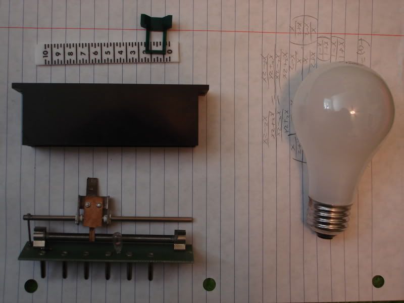
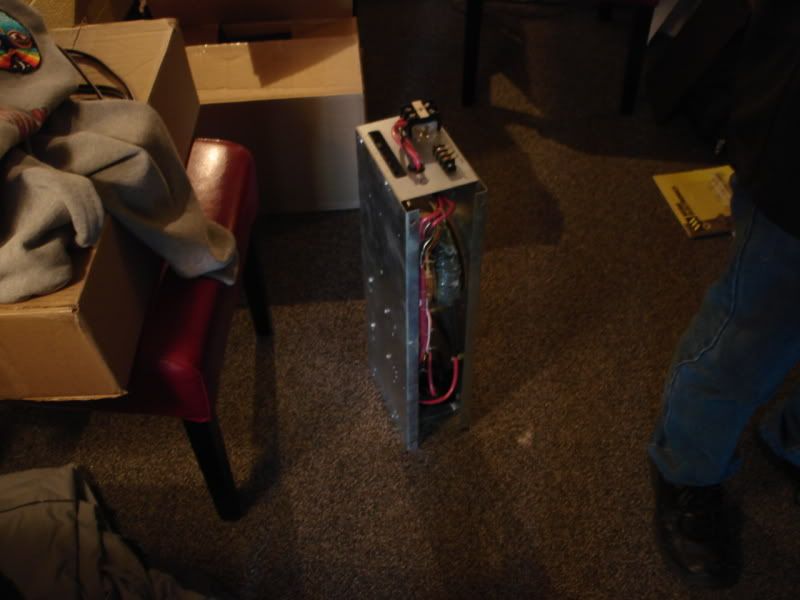
Now on to dimmers. The dimmers themselves were interesting. The modules were essentially a control card, an SCR on a live heatsink and a choke coil wrapped in a steel box, open on the top and bottom. Here's one sitting in an office after being removed:
Photobucket

There were thirty of these, plus ones for the house lights placed into a large blue steel cabinet with a circuit breaker box on one side of it to cut power to individual dimmers. The house lights could be controlled from a number of different remote places, and this cabinet also contained the circuitry(relays!) for that function. What I loved about it was the way in which the dimmers were suspended in the cabinets. Essentially, there was a horizontal metal rod in the front of the cabinet and one in the back that the dimmer would teeter on. A little piece of metal at the front would hold the dimmer to the front bar with a small screw. There was no way of removing a dimmer without having it crash onto the dimmer below it first, which is great when you want to remove one live. Especially with those exposed live heatsinks on the SCRs.
The best part of the whole system was that after trying all of them, we realized that only about 10 of the dimmers actually worked properly. By the time it was retired, only about 5 of them worked. Luckily, they were all about 6KW dimmers, so sometimes an entire scene could be placed on one dimmer.
The last interesting part about the original system was what I call the "high voltage patch." I have seen many of these in pictures. Many of them employ a "plugboard" approach; looking like an old fashioned telephone switchboard. However, Stage-Brite made something very interesting. Essentially, it was a matrix switch. Any one of the ~90 lighting outlets could be patched to one of the 30 dimmers with the positioning of a slider.
Photobucket
The picture here isn't very much good in giving a descriptive look at how the system operates, but the lighting wasn't very good on stage right where this thing lived. However, a picture from a Canadian museum I found recently shows one outside of its casing:
Photobucket
This picture was posted on its side on that website. Must've thought it was a console...
Circuit breakers on both sides cut off power to the individual outlets to allow for patching. Selections were made by slightly pulling out the little sliders and moving them sideways into position for the proper dimmer. When I saw it open on demolition day I thought it was one of the most clever things. Before I knew any better, the first time I saw it I did in fact think that it was the lighting controller. You can still find the patent for it out there, I believe US#4,041,257.
Our panel in particular was fun, for nothing could be patched to outlet number four. If something was, either a buzzing noise or an ember would be drawn out of it. Never did figure out what was on that circuit (it was up in the proscenium).

towards the end, the board was replaced further. Another facility with a similar, as a matter of fact, duplicate, system gave us a DMX512 to analog controller. In the process of installing it, we lost some of the dimmers because some were not into dealing with the change from -24vdc to +12vdc control voltage. After this I believe we had 7 left that we were able to control with an ETC X/Y board.
The facility that gave us the converter had all of its dimmers functioning properly. It even had the original half of our type of console. It was the only time I got to see something like it in person, not in a drawing. It was being removed, but in retrospect I can't seem to understand why we didn't replace our dimmers with their functional ones(they were offered). Or even try to get the board back operational with their console. Between all the plug-in fader modules we would've had we could have probably completely restored it. Such is life.

The most creative thing I did with that setup was during a music revue that we put on every year. The ETC board was laid over the dead parts of the Stage-Brite console. The SB console only could operate house lights and non-dim channels at this point. The band performing was up on a platform which had diffusion put in the front of it and an array of red, blue and green lamps placed behind it. Patching the lights into the floor outlets and then the non-dim channels, I was able to flick the lights on and off in sequence, or however using the remaining non-dim toggle switches. Not too sophisticated, but not bad for a (at this point) 5 channel lighting board.

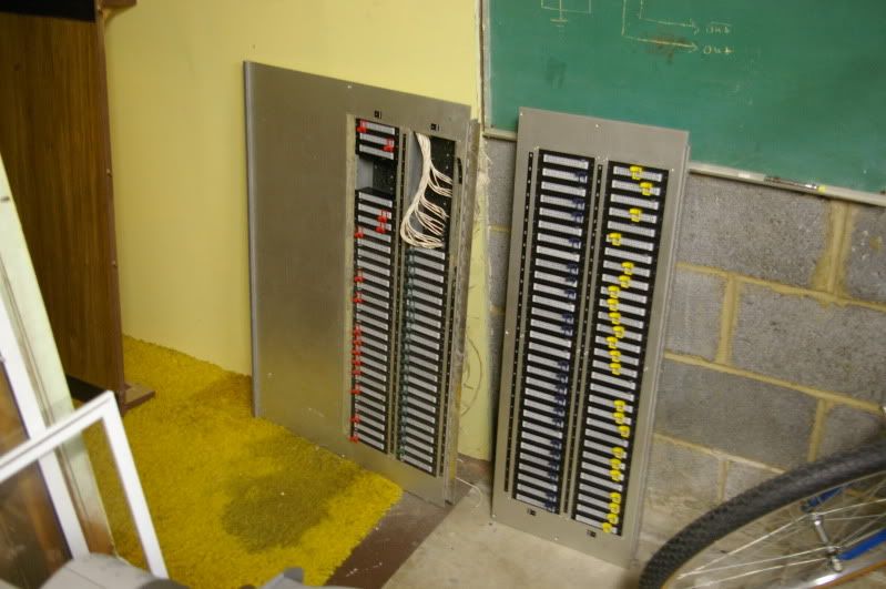
Eventually the system was removed from the facility and I got to keep a few pieces of the board. All of the original preset panels are stowed in my basement:
Photobucket
I also have the little lamp that was part of the board and can be seen above, and the Simpson meter from the test circuit of the high voltage patch.
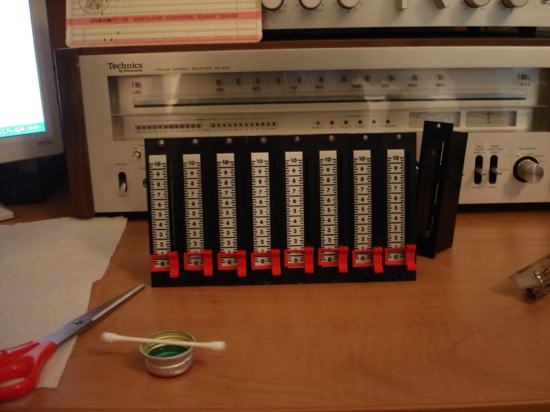
The plug-in faders are very nice and quite well made. I spent a good time restoring all of them, the smaller panel right now as a display piece, the larger panel perhaps to someday be used again for something. A few pictures of the restored faders:
Photobucket
Photobucket
The faders are lit with a small bulb operating on 24vac. The sliders are really nice, especially now that they have been cleaned and lubricated. Sadly none of the other system was salvaged, and the components I have are the only ones left of either system. All I guess I can say at this point now is that it wouldn't have been a bad console if it were cared for a little better. However, despite that it sure gave us some fun things to talk about today.

Monday, October 10, 2011

Update of the Last Two Months

The past couple months have been a bit hectic. Once I was ready to start the recording project I was gearing up for, everyone became unavailable and then it was time to go back to school. School for me is four states over and can get pretty hectic when you're taking 17 credits and working at a television station part-time. Before I left I did finish up a few projects and take pictures of them. They will be up very soon. Some new equipment has come in too, such as a new pro video camera and a four-track open reel deck! I'll be right back after I tackle this paper and midterm...

Thursday, July 28, 2011

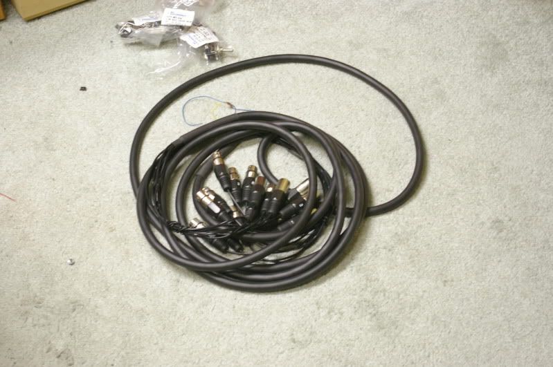
Agh! A Snake!

Photobucket
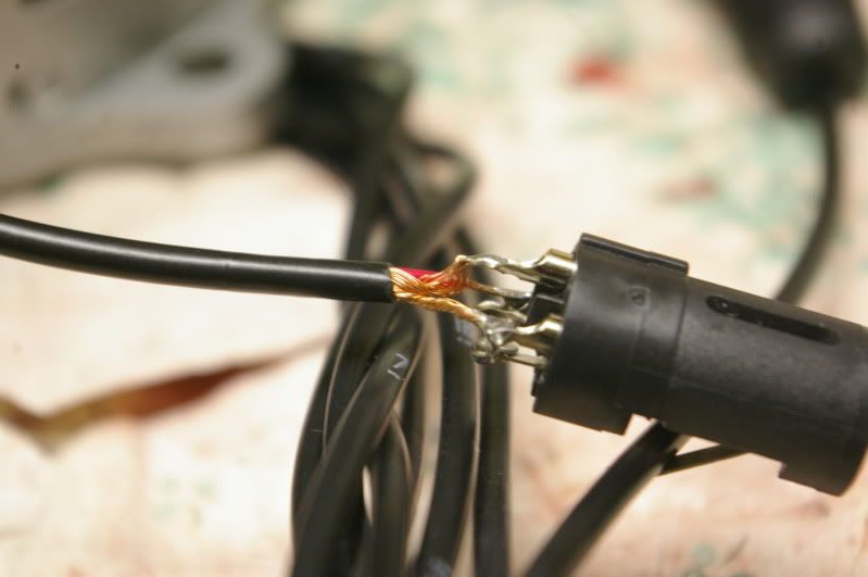
A while ago I was talking about purchasing a microphone snake and had decided to buy a $40 one off of eBay. It arrived a little while ago, but I soon realized why you don't buy $40 snakes off of eBay.
Photobucket
The above was one of the female connectors on the snake. I decided to take a quick look at one of the connectors, just for the hell of it and I am sure glad I did. You can see in the picture that the cold lead is so stripped that you wouldn't even know that it had insulation! Other connectors had too much insulation stripped off of them so that all the leads were shorted together. At least I didn't wait until the time of the recording to find out that the snake was unusable. Luckily the company was willing to give me a 15% refund on the product so I can repair it myself. But this only came after I accidentally gave them my school address and had to have a friend send it back to me, even after telling them about the mistake and them telling me it was all taken care of. Oh well, buyer beware I guess. This is what I'll be working on today.

In other news, I took the WV-V3 outside to see how it performs with good light. I used the alignment card with the now-fixed manual iris knob and the results aren't too bad.


However, I did notice that there may be a burnt-in spot on the blue tube, because there is a yellow spot in the lower middle left of the image. You can see it best near the white cross-fence in the video. I don't know when it happened. I hope it wasn't because of my efforts. I do have to admit though that I was somewhat wildly throwing the iris knob around. The spot does seem to appear in some earlier footage that I took without aligning the camera and before I threw it into manual iris. Oh well.

Wednesday, July 13, 2011

It's Been a While....

Hmn, I haven't been good at keeping this updated recently. Not a terrible amount has happened though. The only really major thing to report on is the progress of the recording project I have. I have finished the KLHs (more on those difficulties in a sec) and am working on microphones. Other than that, I am just about ready to go with it.

For now though, the speakers.

For the most part, The speaker restoration went without a hitch. I had some issues securing things (I used the same adhesive caulk from the speaker sealing) and then a major issue with one of the tweeters. But the restoration of the electronics went well enough.

Pictures of the finished crossovers:

Photobucket
Photobucket

I had realized that whoever had tried restoring these speakers before me didn't realize that they had to be careful when returning the speaker lugs to the aluminum backplate. A couple fiber washers were missing so that the speaker was shorted out completely by the backplate. I got a bit creative and used some old perfboard instead, as I have no rubber or fiber washers.

Once the electronic restoration was done, I put all of the insulation back in them, hooked up the drivers and then tested them. To my horror the right speaker had no high end. The tweeter was inoperable. Frantically hoping that the tweeter was not blown out, I took apart the speaker and tested the tweeter with a meter. It was blown. Somewhere. Luckily, upon closer inspection I figured out that the part of it that was blown was the little wire that runs from the speaker lugs to the voice coil. Using a bit of wire from an old AC gearmotor I was able to mend it and so far my solder job has held up.

In this picture you can just see the broken wire and where it is supposed to connect, it's towards the middle top of the speaker:

Photobucket

After this point I was a bit too anxious to get it working to take any more pictures of this process. But I did clean up the cases with some wood polish and they look damn good again!

An after/before shot of the speakers:
Photobucket
(I seem to have an issue with always putting the before on the right for some reason...)

Now these speakers have replaced my home-made ones on top of my desk. They sound really good, but I can't tell if one is slightly louder than the other. It may be the amplifier though... either way isn't good, but oh well.

As far as microphone building goes, the speaker microphones are almost done. I just need to just some holes in the cases for the connectors and then bolt the elements into place, so those are pretty much done.

The condenser microphones are still a mess though. They are still sitting in pieces on my deck. They need to be sanded and then assembled.

The cases for the speaker microphones:
Photobucket

Other than all of this, I have a small project I am embarking on that I haven't done much with yet. I guess because I'm lazy. A small rack mount with a power strip and KVM switch in it to control all the computers in my room.
Photobucket
I want to first modify the power strip so that each individual plug on the back has its own switch so that I can turn the computers on separately from the console. This is what I have been putting off.

The decision to include it in my setup came when I decided to try and build a CD/DVD duplicator. I have an old server frame that has 5 drive bays on it, so I figured I could pop a bunch of drives in and use it as a duplicator. This need arose when I was thinking about ways I could possibly produce a record or film and distribute it. This would increase the number of computers in my room to about four, so I figured it would save a ton of space.

The frame of the server case:
Photobucket

And since Black is the new beige in the computer realm, I have been updating the case with a little "canned style":
Photobucket

I'm also thinking of using it for a transfer machine. Such as transferring old audiotapes and possibly videotapes to a digital format, with the ability to make multiple copies. We'll see.

That's all for now, but coming up I think I'll do a post about the snake that I recently received, an update about the recording process (hopefully this weekend!) and then a long post about one of the best audio effects in the past 100 years, echo. Stay tuned! (I swear it will be quicker this time...)

Thursday, June 23, 2011

Recording Update

In order to gear up for recording my friend's band, I have started buying/renovating some of my equipment. From last post I decided to just buy a snake and make a few XLR cables because I had some extra wire from my last cable-building adventure that will get me 3 20' XLR cables, two 5' XLR-1/4" cables and a 5' 1/4"-1/4" cable. After all the cable supplies arrive, all that's left is just building the microphones. I have started on the speaker microphones but I am holding off on the condensers until the mixer shows up so that I can experiment with the circuit I will use.

Other than that, I have started restoration on a pair of KLH-17s that a roommate gave me for free. From what I have heard they are a good speaker to restore and the restoration has only cost me about $20(and that's a high estimate). When I received the speakers, only one worked. One speaker sat at about 8ohms (which is proper) while the other one sat at around 3 or 4ohms and would not produce audio at all. In order to even use these speakers, this restoration was necessary. The restoration includes replacing the four capacitors in each speaker and sealing the speaker surrounds with acrylic caulk because they are cloth, not rubber. I am following the restoration procedure posted here: Renovation of my KLH 17's is complete However, I think that this guy's speakers may be a bit younger than mine because he has different looking capacitors in his. The crossover network is still the same though.

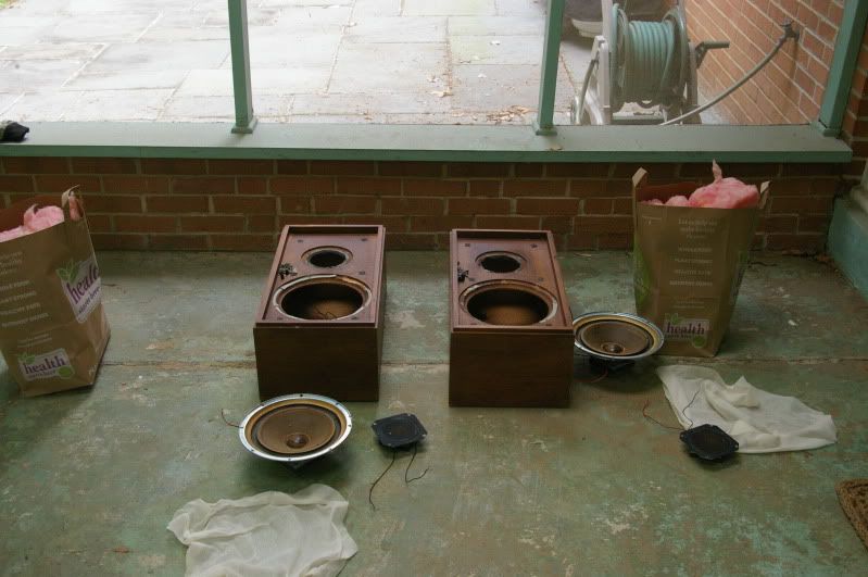
Photobucket

I'm doing the restoration outside on my porch because the speakers are filled with fiberglass insulation that you can see in the shopping bags in the above picture. Sadly though, I'm sure the speakers are not enjoying the Maryland summer.

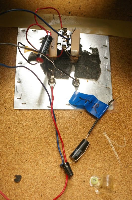
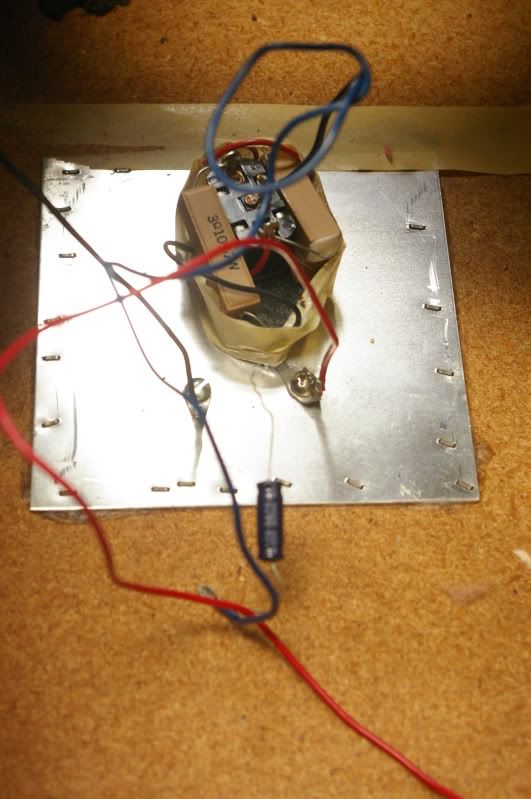
Taking a look into the speakers at the crossover network, it appears that one of the speakers may have been tinkered with before:


Photobucket

Photobucket


The speaker on the right has had one of its capacitors changed out. The original capacitor in the speaker was a dual-type. I'll be replacing them with four individual capacitors. The previous restorer replaced the dual 4uF cap that was tied in parallel with itself with an 8uF one, But it's a cheap little 16v electrolytic. Hopefully paying a lot more for higher voltage caps will help it sound better. One can only hope. The electronics aren't that complex and I'm not too worried about them.

As for the sealing, it wasn't too difficult. However, I was just squeaking by at the end because I just about ran out of sealant. I had made a mixture of acrylic adhesive caulk and water (about 1:2) that I applied with a glue brush (as instructed in the restoration post). This actually went very well. I'm not entirely sure that the speakers needed it, but a datestamp on the inside told me that the speakers were manufactured in 1966, so maybe it was time.

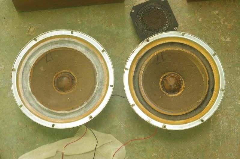
A before and after shot of the speakers while I was sealing them (after/before):
Photobucket

I'm still waiting for the parts to come in, but for now there isn't anything to do, it really is a simple little project. I plan to use these as the control room monitors for when I record. They are probably the best speakers I own, the only others being a pair of home-made ones that I bring with me to school. I don't know the response of them though and they have little bottom to them. Those I'll use as the studio monitors for talkback and playback to the band.

Sunday, June 19, 2011

Recording Gear

So, I know I said I was going to clean up my workbench, which I did, but it is now covered with whatever I was working on on the floor. It is now covered mainly with the innards of the Akai deck. And it's a wreck again. I don't have any new pictures as of yet, but since I haven't been providing any new posts, I thought I would at least do a quick update.

What has been consuming my mind the past week has been gearing up for a recording session. A friend of mine has a band and I have volunteered to record them. This requires me purchasing and building some equipment. The main things I need are more microphones, more cables, possibly a snake and a mixing console. I have been spending many hours with excel spreadsheets trying to figure out the best way to make all of this at the lowest price. Luckily for me, the cheapest priced XLR ends at allelectronics.com are the switchcraft type, which is highly unusual but awesome because they just look SO COOL. Currently you can make a 20ft XLR extension cable for $10.90, but they sell a pre-made one for $8.50. I don't know if the quality would be the same, but as of now I am in a bit of a bind with those.

Microphones are more interesting. I have two beat Electro-Voice RE-15s and a 635a, but I would like some condenser microphones to use as well. I've heard that the elements that you can pick up at radio shack aren't bad and give some pretty good response, so I am going to try working with those a bit. The other thing I have been experimenting with is using speakers as elements. I had set up one speaker a while ago to use in this fashion, but it was very tinny. However, while testing it recently I decided to see what the ones out of the Akai sounded like and hooked them up. They actually sounded superb, kind of rough but not really airy like the other one. So I have two winners. I also grabbed a couple of high horns that I had lying around and they sounded good too, at least for giving a high end to the sound. The way I see it is that they are operating exactly as they would as if in a speaker, good for what they were designed for, which shouldn't really be surprising. So I currently have 3-4 speaker microphones to build and I'm looking to build 4 condenser microphones.

As for the mixer, I just bought one. I looked into building one and it looked like I might be able to keep it around $100, but in the end I decided to pay a little more (well, twice) to spare myself a long process of building something that I don't have much experience making and that I need somewhat soon. The mixer that I bought is a Mackie 1402 VLZ. It's a 14 channel (really 10) mixer with 6 XLR inputs and 4 stereo 1/4" inputs. What's good about this mixer is that I am familiar with it, know that it's good and it's ready as soon as it arrives. It's also brand new and came with a custom case! The only downside is the XLR inputs. There are only 6 of them. My plan was to use 7. Oh well. Maybe the condenser microphones will come out a little hot and I can plug them into a line-level input. We'll see. It's either that or probably DI the bass.

Now that the mixer is out of the way, the only hard part becomes the cables and snake. To get some good separation, I want to be somewhat far away from them performing. This either requires me making 7 really long cables or making a snake. Currently, to make new, long cables it would cost twice as much as making a snake with a multi-core cable. However, the only multi-core cable I have is a long (~30ft) unshielded cable I found that was used for phone lines. I have been toying with the possibility of using this unshielded, but I need to do more tests first. I also toyed with making it a phone-phone snake because it would be cheaper and would allow me to ground all the wires of the unused lines using jacks with switches in them. However, I would NEVER be able to use it with phantom power, which wasn't a problem until now, seeing that I have just bought a mixer that can supply phantom power.

Experimenting with the cable the other night, I could only get a good sound out of it with the cold lead shorted to ground and still picked up the local AM radio station. We'll see. It may also just be easier to bundle a bunch of cables together with tape. It will cost a bit, but at least it will work better. A 20' 8-core snake would cost ~$52 with regular mic cable. With ends it's $72. Bundling AllElec's pre-made cables together costs $68. Although at these prices I may as well buy the ones on eBay going for $40. However, If I can get the multi-core cable I have to work, I can make it for $22 not including the wrapping for the loose ends on the mixer side.

But enough of that.
Following is the status of projects that I have previously reported on:

Panasonic WV-V3-
Still misaligned. I temporarily fixed the manual iris control and tried getting the light levels up pretty high to do an alignment. However, I couldn't provide enough light and the temporary knob broke off (not the right screw to hold it). I am waiting for a day where there is a lot of sun out so that I can use it to bathe the test chart. I worry that the adjustments I made to it put it in a place where it can't align itself because it's too far off to compensate. A manual costs $50. I don't even know if this camera is still worth that.

Variac-
I haven't worked on this much at all. The main thing holding me up is that I need to buy a power switch. Once I have that I can wire it up and then finally test it out. This isn't really worrying me, I'm just waiting until I can buy a bunch of things at once from probably AllElectronics.com ($7.00 flat rate shipping can be difficult sometimes).

Akai X-1800-
When I took it apart I finally found out what was probably the problem with it. The head amplifier sits on a card that plugs into a mainboard along the bottom of the electronics package. One of the sides of the edge-plug, the one that holds the card to its contacts, had broken off, possibly causing broken connections. Oh well, I have another open-reel deck.
The parts are still littering my workbench. I'll probably salvage all of the mechanical bits that I need and then put the rest into the scrap bin. The bits will then probably just sit in the videocorder's case for the time while I deal with recording the band.

Thursday, June 9, 2011

These Past Weeks

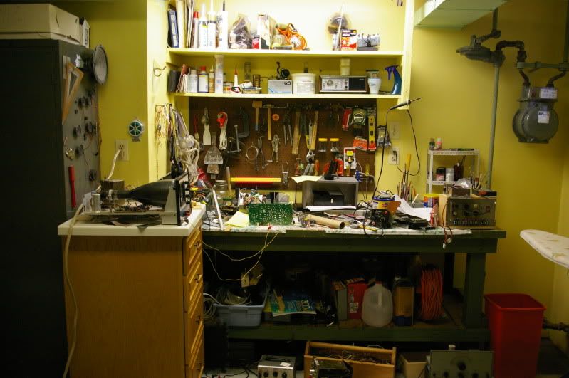
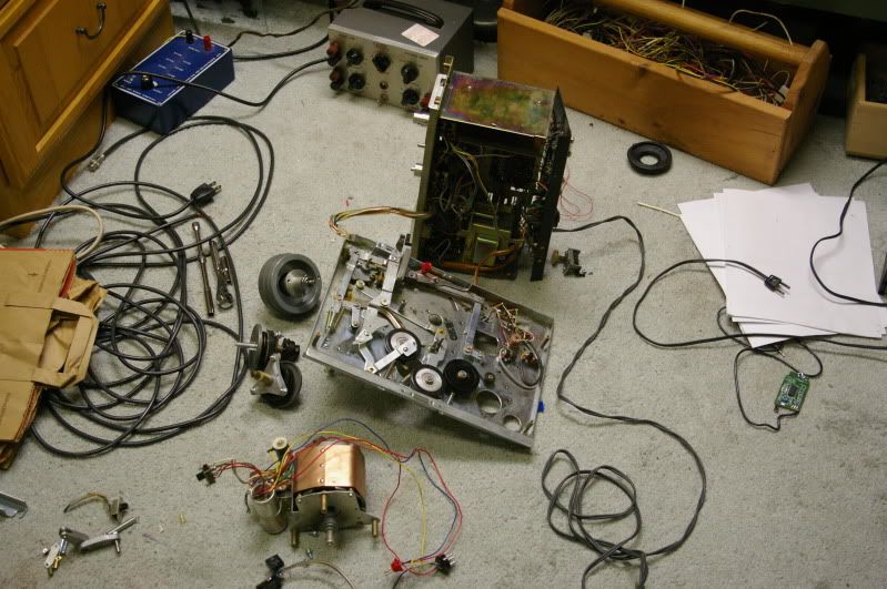
So this is the state of my workspace:
Photobucket
It's pretty bad. It's also why I haven't been getting much done. I didn't clear it off after I got home from school, so the workbench was already pretty cluttered to begin with. Cleaning this mess up will be what I'll be doing for the next week probably (also my room too, it's also filled with electronic whatnot).

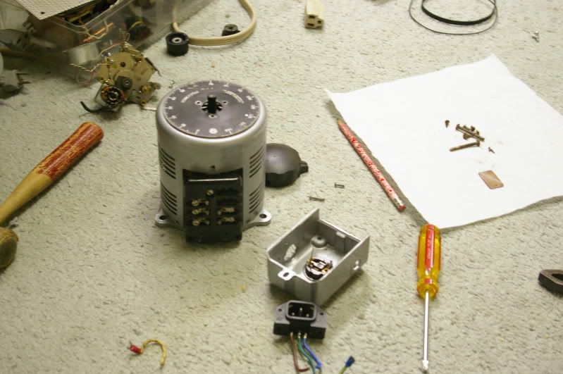
In the meantime, I did work on one project, this little Powerstat Variac:
Photobucket
It was in really bad condition when I found it. I don't have any before pictures from when I had just found it (I started on it while I was in school) or any when I started restoring it. Suffice to say there was a lot of rust and corrosion covering it. I spent a lot of time with a wire brush and vinegar trying to get the surfaces good to be painted.
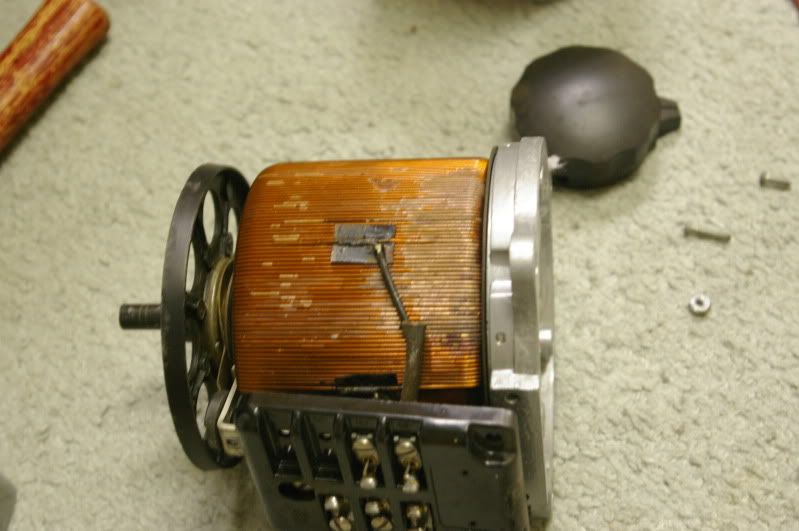
The only thing that worries me is the coil itself. There were some spots where it had really bad corrosion that I had to somehow seal. I decided that the best way to do this would be to seal it with wax, but now I realize that if the coil heats up a bit, the wax may just melt off. The picture below shows the worst region after it had been sealed with wax:
Photobucket
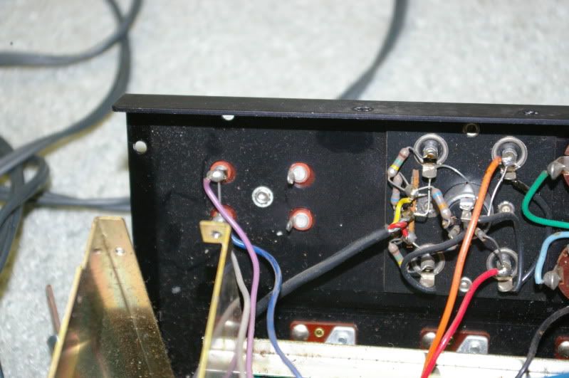
Lastly, while I was pulling the electronics of the Akai further apart, I noticed a couple terminals that didn't have wires on them:
Photobucket
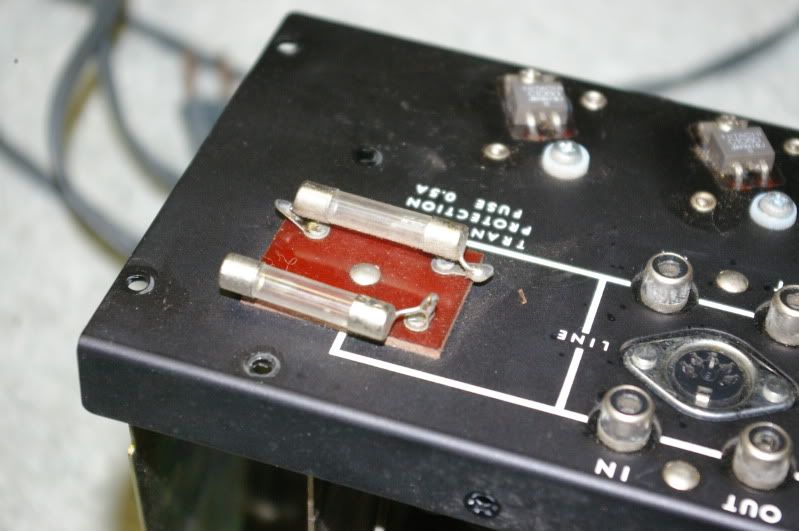
On the other side:
Photobucket
"transistor protection fuse" This makes me think that sometime when I was poking around in there I broke a wire off that went to these fuses, therefore rendering the amplifier useless. However, I can't for the life of me find any loose wires. So this continues to be a mystery. Doesn't matter too much though because of the state of the transport mechanism:
Photobucket