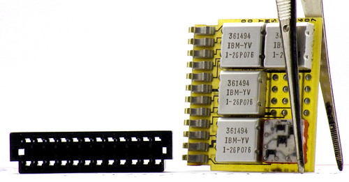
When IBM introduced System/360 they also announced an entirely new circuit technology called Solid Logic Technology or SLT. It was spawned out of the desire by IBM to make ever-more miniature parts to put in their computers. Integrated circuits was what everyone seemed to be looking forward to in the early 60s and IBM did a good amount of research into development of ECL logic being implemented on a single chip. This research proved successful, but it wouldn't see use until the 70s. Due to the reliability of producing small silicon transistors individually on a large substrate and cutting them out, IBM decided to use a "hybrid circuit" technology for the System/360.
IBM developed individual, minute planar silicon transistors and diodes with a glass backing that they would then affix to a 1/2 inch square ceramic chip. The ceramic chip had 12 pins on it with printed metal traces that made connections between the pins and the transistors and diodes. Resistors were constructed by depositing carbon ink between two traces and trimming them to the right value. These little ceramic chips would be coated with a silicone gel, then covered with an aluminum cap and potted underneath with rubber. This is the hybrid package. Most anyone would call it a silicon chip, but it's not an integrated circuit as we would think of today. Each chip consists of anywhere from 0 to 4 transistors or 0 to 8 diodes and a number of resistors. They are built so that the individual components can be isolated and tested.

A diagram of the glass-backed transistors and dual-diode devices. They are flip-chip modules resting on copper balls to make contact with the ceramic substrate.From the SLT Designer's Handbook
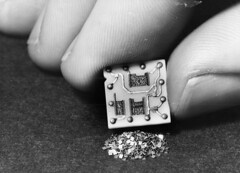
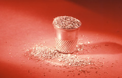
SLT was actually quite an improvement in miniaturization. First a 'chip' with some transistors or diodes and a hand for reference. Second, I've heard that "this is a time where 1000 transistors overflow a thimble"
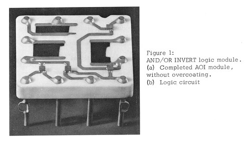
A bare SLT chip shows the mounted transistors and diodes as well as trimmed carbon resistors.
These chips would then be assembled on fiberglass boards to form a logic function. The amount of gates on a single card are equivalent to that of a 7400 series logic chip. It is not very dense. IBM's 360 and Early 370 Systems mentions that when the system was first announced, the low-density logic was criticized as being behind the times. It absolutely was, but when the reliability tests came back they found it was much more reliable than what was the cutting edge, what IBM had rejected initially for this exact reason.
Looking at how IBM made these cards, it's hard to see how they could fail. The fiberglass backing is fireproof and resistant to moisture. The aluminum covering the chip won't corrode. And there are multiple layers of sealant on the transistors. In order to reduce issues caused by bad spring contacts, IBM put the female connector on the card. The backplane it plugs into is just a grid of gold-plated pins. If a spring-loaded contact goes bad, it is part of the card- so replacing the card fixes the problem, better than having to diagnose and replace a broken card slot.
Also, every single contact is gold-plated. The pins on the backplane are and the Beryllium-Copper spring contacts on the card have a huge pad of gold on the end of each one:

The pin spacing on all of these boards is 1/8 inch. Numbering of the socket pins is based on the backplane, so some weird pin numbers are found:
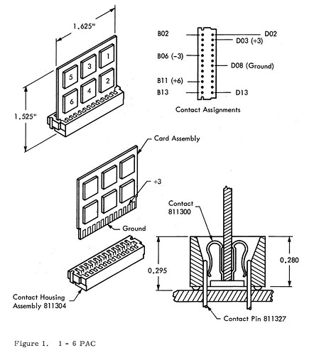
There were Double-height boards as well as double-width boards including a double-height double-width board that held 24 'chips.'
These cards were mounted on backplanes about the size of a standard sheet of printer paper. They contained gold-plated pins and a plastic mold that the cards fit into, preventing misplacement. The backplanes were multi-layered with power distribution and some signal lines, vertical paths on the back, horizontal paths on the front with the cards. Additional connections were made using wire-wrap. These backplanes would then be assembled into a "gate," possibly 4 by 5 planes in dimension. These were all connected by laminated ribbon cable that ran through channels next to the cages built around the backplanes.

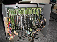
A great example of the whole SLT gate in action. The backplanes, ribbon cable and card cages can all be seen inside this model 67 at Newcastle University.
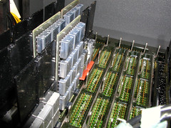
A close-up view of a backplane, shown alone in a diagnostics box. Note the metal bar that acts as a support and registration pin for the card.
I own a number of SLT cards that I bought off of ebay a while ago. They have been a source of inspiration for producing my own SLT cards, but also serve as some great, fun display pieces. Working with a number of different documents about SLT from Bitsavers, I have managed to figure out what different circuit types are on the cards that I have. What the cards themselves do are a little beyond what I have been able to figure out. Knowing the chip circuits and chasing the traces on the board would however tell a lot about them.
Most of the boards I have consist of three types of logic chips: 361493, 361494 and 361495. In order they are an and-or-inverter, a direct coupled inverter and an and-or extender. This leads me to believe that the cards I have are bus drivers and gates. They are all low-speed, so maybe they are from a peripheral device or smaller model system.


Schematics of the individual modules, in ascending order.
A look at all the boards I have:
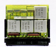
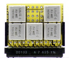

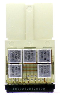
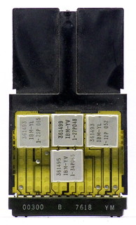
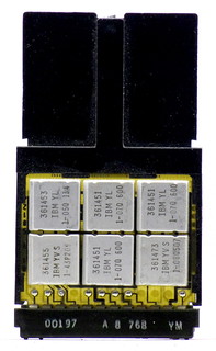
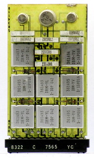

Last, a view of one card, the one pictured at the top with its connector loose. One of the metal tabs that holds the plastic molding on the connector was missing allowing it to slide off relatively easy. I decided this would be a good board to uncap an SLT module on, as it was no longer mint. It gives a good view of some things you can't see from the documentation.
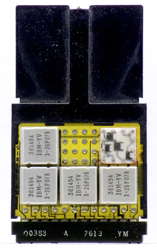
It is a duplicate of the top right card in the above set of photos.
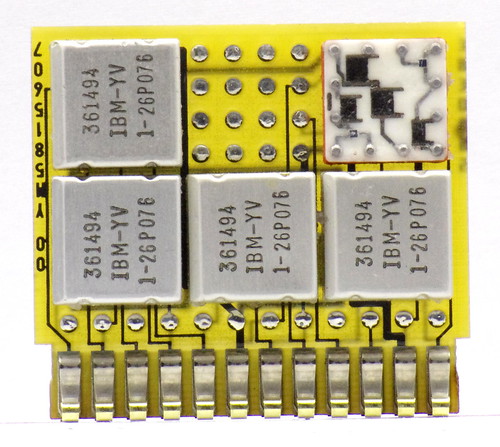
With plastic flag and end connector removed, the shape of the board and its traces can be seen better. Silicone gel has been removed from the chip to better display the components.
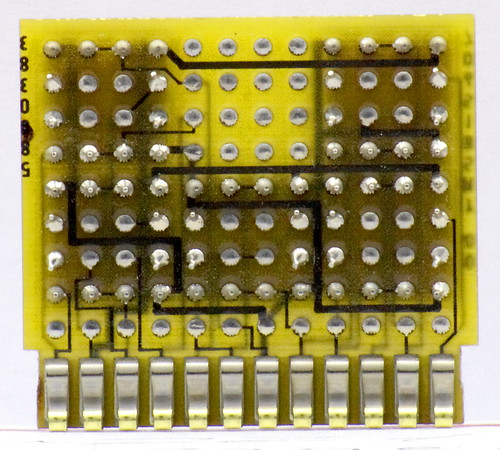
A rear view. In both of the above photos it is easy to see that the connector is a part of the board. The plastic connector only serves to guide the pins on the backplane to the pads on the connectors. But just look at all that gold!
The connector seen on these cards had an exceptional lifespan for IBM. Even the 1/8 inch spaced boards and backplane technology did. IBM was installing 4-wide boards in this style as late as the 80s. Although, by then they had been using more standard types of chips, called Monolithic System Technology, or MST. Still packaged in aluminum cans, but with more pins and one little chip of silicon. SLT also got a trip to the moon. Or at least helped get people there. A hardened type of SLT was used int the Launch Vehicle Digital Computer of the Saturn V rocket.
I have learned a lot of this information in a quest to recreate SLT cards. Initially it doesn't seem that hard. The logic can be made using surface-mount components (if you don't mind not having them in fancy little cans). Also, in theory the connector isn't that hard, pins on the board, a receptacle on the card. But it's not a standard pin-header. It's a 1/8 inch spaced connector that is specially molded to fit a particular socket. I have made CAD drawings of an approximation of the plastic molding, but that still leaves contacts to make. I had for a while toyed with making SMS cards because if you also used surface-mount components you would have enough room for capacitors and resistors to get the right response from modern transistors and also never have to drill the board because they're one-sided. But then, you need a 1/8 inch card-edge connector with wire-wrap pins. And they're hard to find...
I consider replicating connectors to be the major limiting factor in reproducing plug-compatible SLT and SMS cards.

Very nice series on the S/360. Thanks!
ReplyDeleteFirst of all let me tell you, you have got a great blog. I am interested in looking for more of such topics and would like to have further information. Hope to see the next blog soon.
ReplyDeleteDiscount Computer Office Chairs
FWIW, TE list as active, a 2x6 way connector housing, P/N 175759-1, that could be useful for making SLT compatible boards. These seem to have a feature for mounting onto the edge of a PCB, but the only contacts available seem to be crimp types, such as P/N 167301-4. However, the mating pin isn't specified, but I'd assume 0.025" square, and I don't know if that matches the SLT backplane.
ReplyDeleteUpdate: TE also list a similar 2x12 way connector, P/N 1-102056-2, which Mouser actually have in stock (ignore their item picture, it's of a completely different connector; indeed, even the picture at TE is of a different connector in the series).
ReplyDeleteWow, that brings back memories; in the summer of 1963 I worked for a civil engineer in Burlington, Vermont and one of our projects was to survey the parking lot at the IBM plant in Essex Junction, Vermont. At that time the plant made switches and its main product was core memory. A year later the new building was dedicated to IC production . A weeks output could shipped in a shoe box.
ReplyDeleteMichael F. Henning
Grass Valley, CA
Just entering the above comment, I remembered that my father in law, Erwin H. Richards was awarded a patent while working at the Essex Junction plant. The patent was for a method of using modulated air to move the dies around the manufacturing area. The US patent was US10881571A, now expired.
ReplyDeleteMichael F. Henning
Grass Valley, CA
https://www.cekaja.com/info/cara-menanam-kangkung/
ReplyDelete> I consider replicating connectors to be the major limiting factor in reproducing plug-compatible SLT and SMS cards.
ReplyDeleteHere is my attempt at making a connector substitute with more readily-available components. I use it for power interconnect inside my IBM 5100 computer: https://github.com/stepleton/SLT_interconnect