Showing posts with label history. Show all posts

Friday, April 11, 2014

Happy 50th System/360! Pt.5: Anatomy of an SLT Card

IMGP4196

When IBM introduced System/360 they also announced an entirely new circuit technology called Solid Logic Technology or SLT. It was spawned out of the desire by IBM to make ever-more miniature parts to put in their computers. Integrated circuits was what everyone seemed to be looking forward to in the early 60s and IBM did a good amount of research into development of ECL logic being implemented on a single chip. This research proved successful, but it wouldn't see use until the 70s. Due to the reliability of producing small silicon transistors individually on a large substrate and cutting them out, IBM decided to use a "hybrid circuit" technology for the System/360.

IBM developed individual, minute planar silicon transistors and diodes with a glass backing that they would then affix to a 1/2 inch square ceramic chip. The ceramic chip had 12 pins on it with printed metal traces that made connections between the pins and the transistors and diodes. Resistors were constructed by depositing carbon ink between two traces and trimming them to the right value. These little ceramic chips would be coated with a silicone gel, then covered with an aluminum cap and potted underneath with rubber. This is the hybrid package. Most anyone would call it a silicon chip, but it's not an integrated circuit as we would think of today. Each chip consists of anywhere from 0 to 4 transistors or 0 to 8 diodes and a number of resistors. They are built so that the individual components can be isolated and tested.
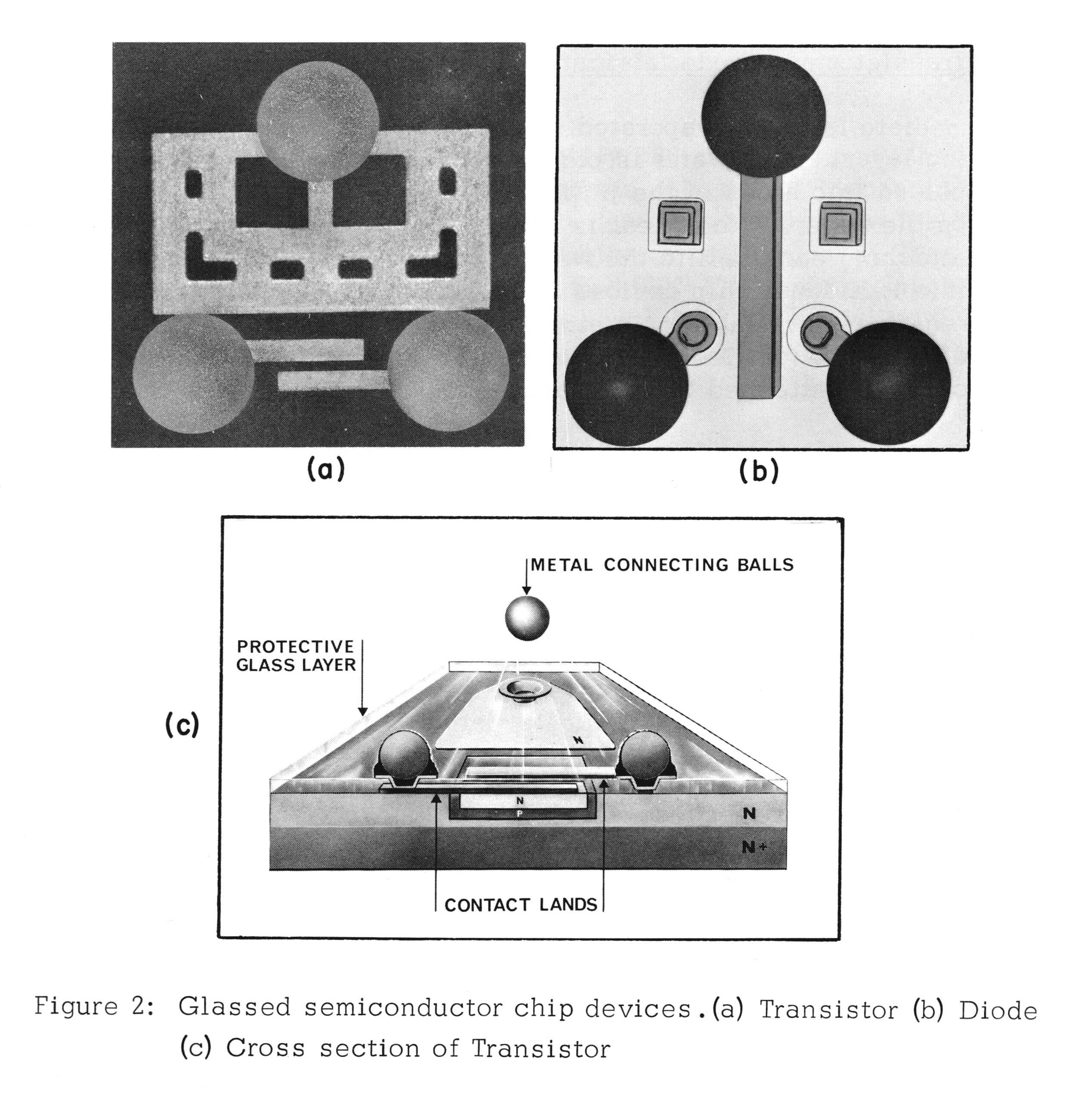
SLT transistor diagram
A diagram of the glass-backed transistors and dual-diode devices. They are flip-chip modules resting on copper balls to make contact with the ceramic substrate.From the SLT Designer's Handbook
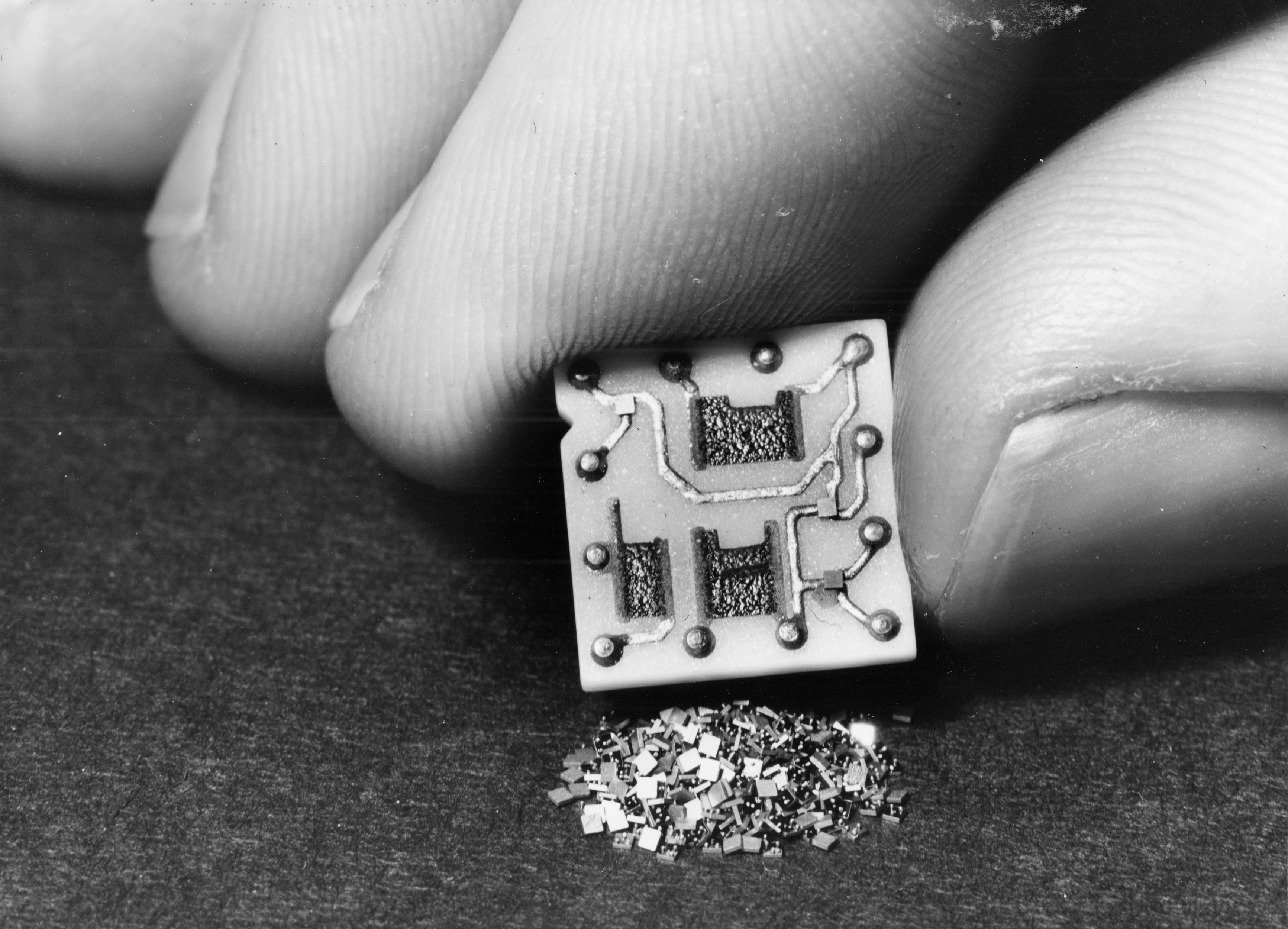
S360_SLT2S360_SLT4
SLT was actually quite an improvement in miniaturization. First a 'chip' with some transistors or diodes and a hand for reference. Second, I've heard that "this is a time where 1000 transistors overflow a thimble"
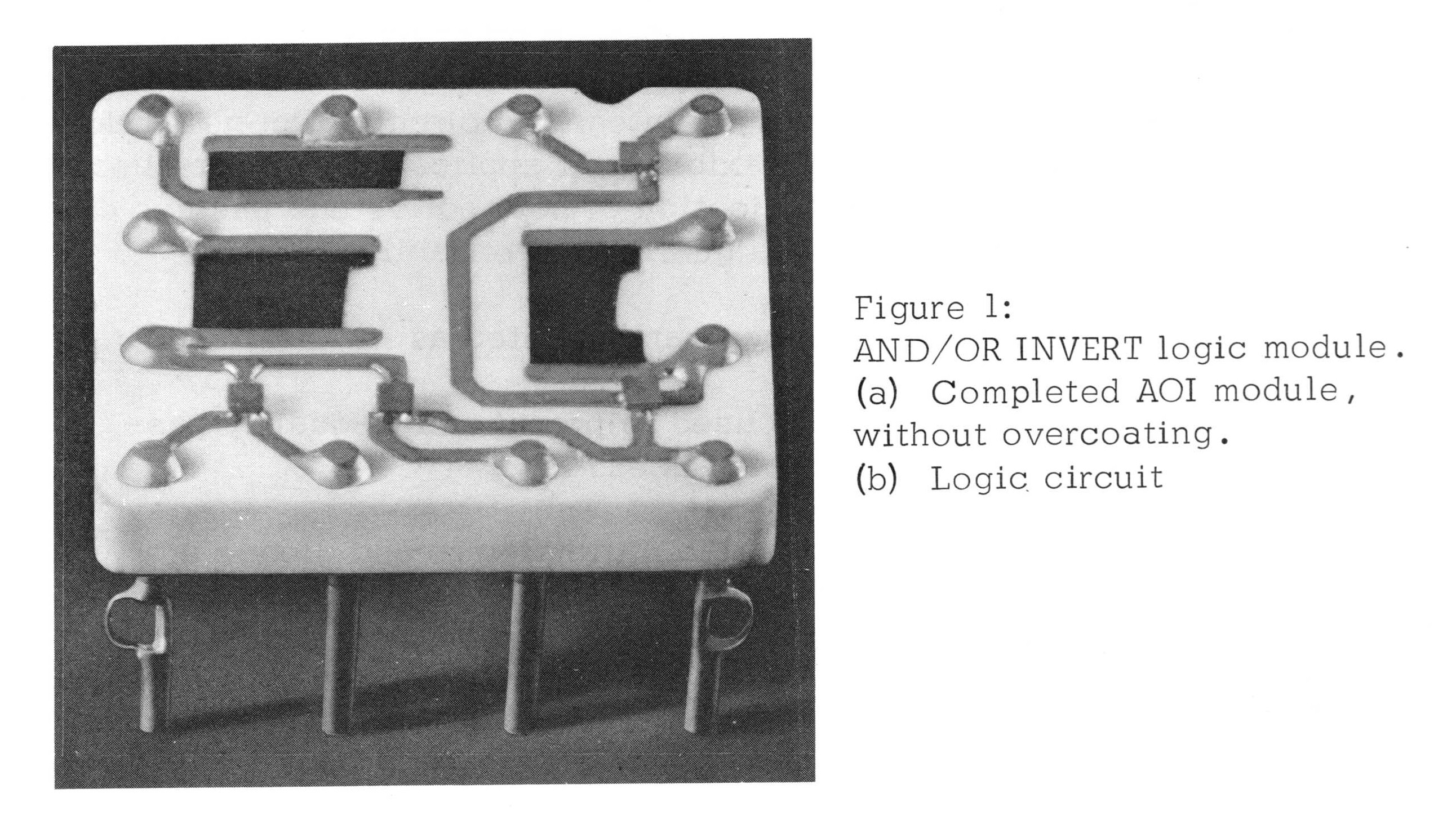
SLT chip bare
A bare SLT chip shows the mounted transistors and diodes as well as trimmed carbon resistors.

These chips would then be assembled on fiberglass boards to form a logic function. The amount of gates on a single card are equivalent to that of a 7400 series logic chip. It is not very dense. IBM's 360 and Early 370 Systems mentions that when the system was first announced, the low-density logic was criticized as being behind the times. It absolutely was, but when the reliability tests came back they found it was much more reliable than what was the cutting edge, what IBM had rejected initially for this exact reason.

Looking at how IBM made these cards, it's hard to see how they could fail. The fiberglass backing is fireproof and resistant to moisture. The aluminum covering the chip won't corrode. And there are multiple layers of sealant on the transistors. In order to reduce issues caused by bad spring contacts, IBM put the female connector on the card. The backplane it plugs into is just a grid of gold-plated pins. If a spring-loaded contact goes bad, it is part of the card- so replacing the card fixes the problem, better than having to diagnose and replace a broken card slot.

Also, every single contact is gold-plated. The pins on the backplane are and the Beryllium-Copper spring contacts on the card have a huge pad of gold on the end of each one:
IMGP4198

The pin spacing on all of these boards is 1/8 inch. Numbering of the socket pins is based on the backplane, so some weird pin numbers are found:
SLT 1-6 PAC

There were Double-height boards as well as double-width boards including a double-height double-width board that held 24 'chips.'

These cards were mounted on backplanes about the size of a standard sheet of printer paper. They contained gold-plated pins and a plastic mold that the cards fit into, preventing misplacement. The backplanes were multi-layered with power distribution and some signal lines, vertical paths on the back, horizontal paths on the front with the cards. Additional connections were made using wire-wrap. These backplanes would then be assembled into a "gate," possibly 4 by 5 planes in dimension. These were all connected by laminated ribbon cable that ran through channels next to the cages built around the backplanes.
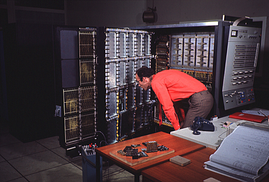
slide24
A great example of the whole SLT gate in action. The backplanes, ribbon cable and card cages can all be seen inside this model 67 at Newcastle University.
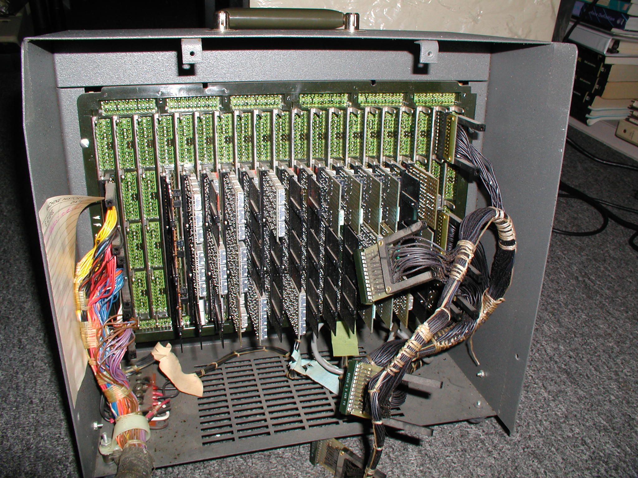
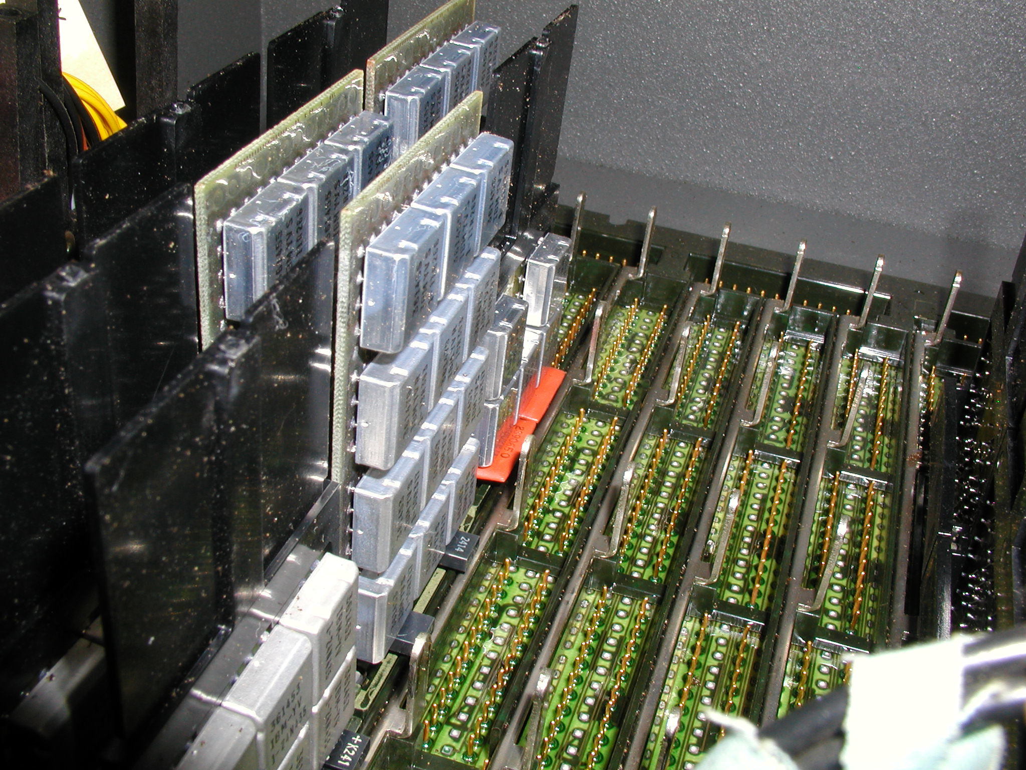
IBM360_SCP_card-cage-6IBM360_SCP_flip-chip-rows-3
A close-up view of a backplane, shown alone in a diagnostics box. Note the metal bar that acts as a support and registration pin for the card.

I own a number of SLT cards that I bought off of ebay a while ago. They have been a source of inspiration for producing my own SLT cards, but also serve as some great, fun display pieces. Working with a number of different documents about SLT from Bitsavers, I have managed to figure out what different circuit types are on the cards that I have. What the cards themselves do are a little beyond what I have been able to figure out. Knowing the chip circuits and chasing the traces on the board would however tell a lot about them.

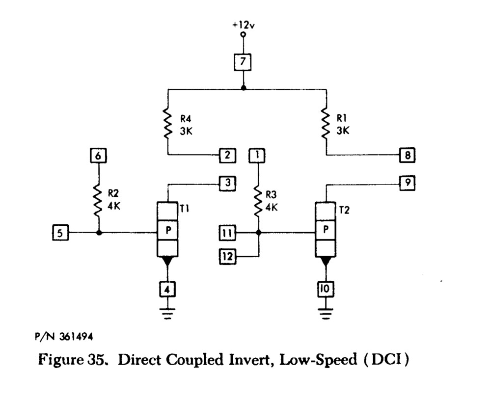
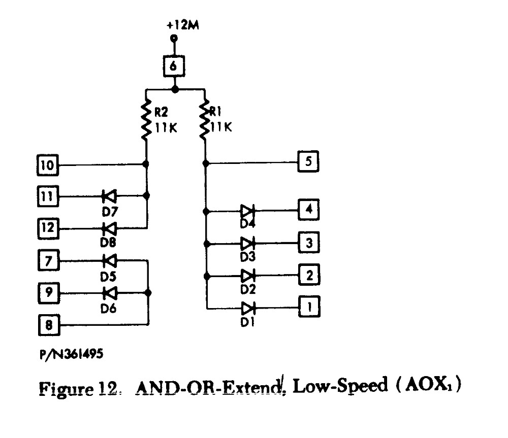
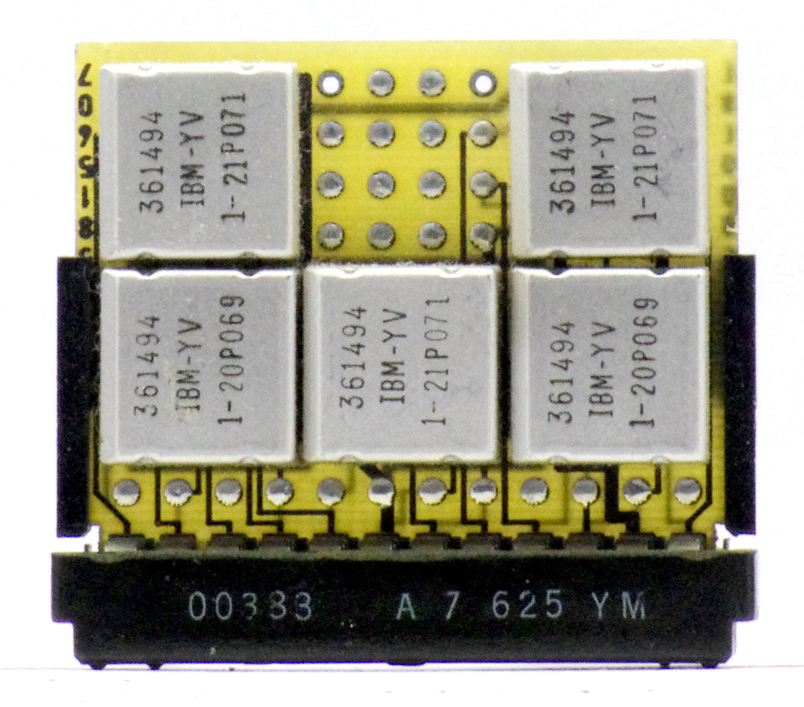
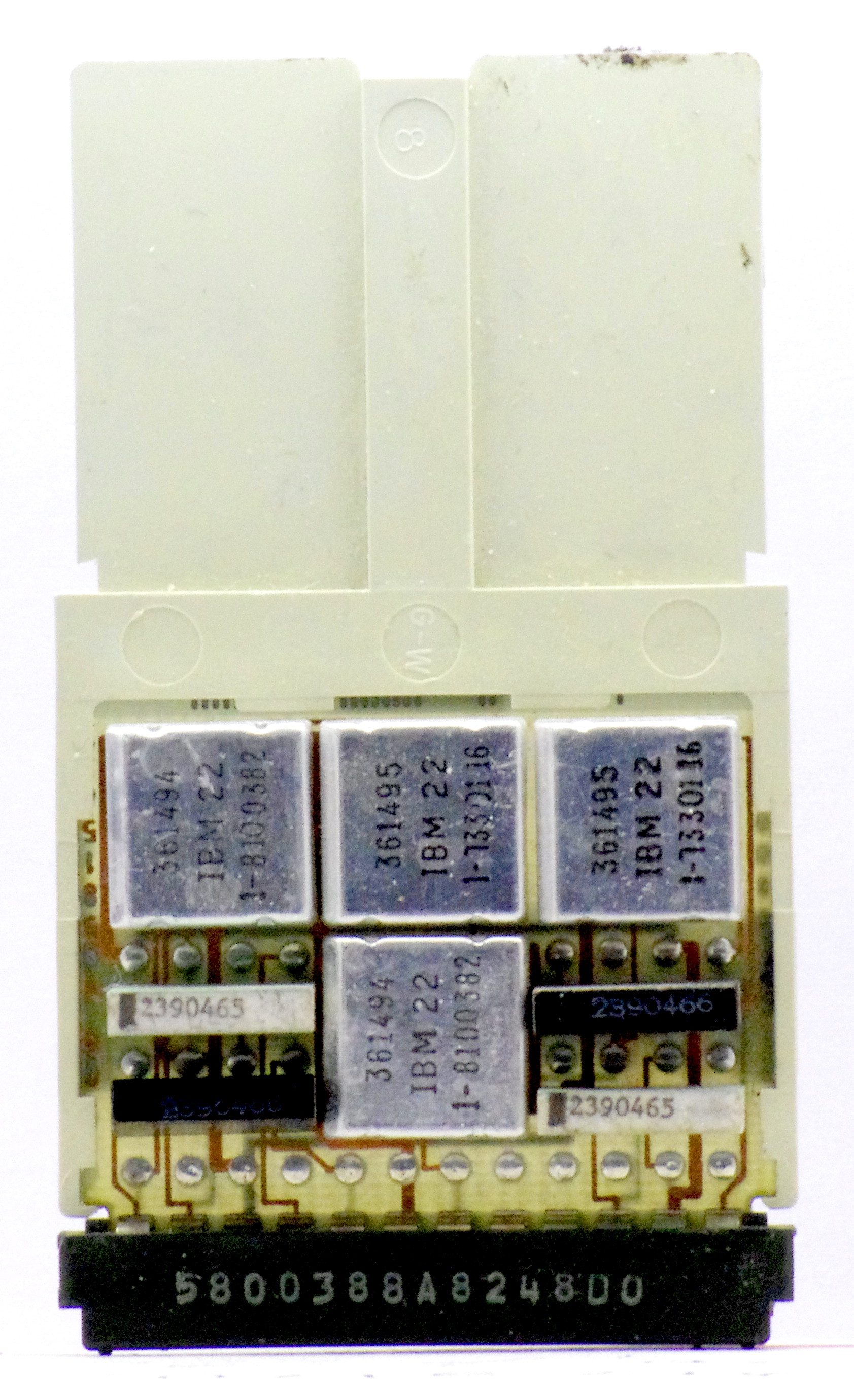
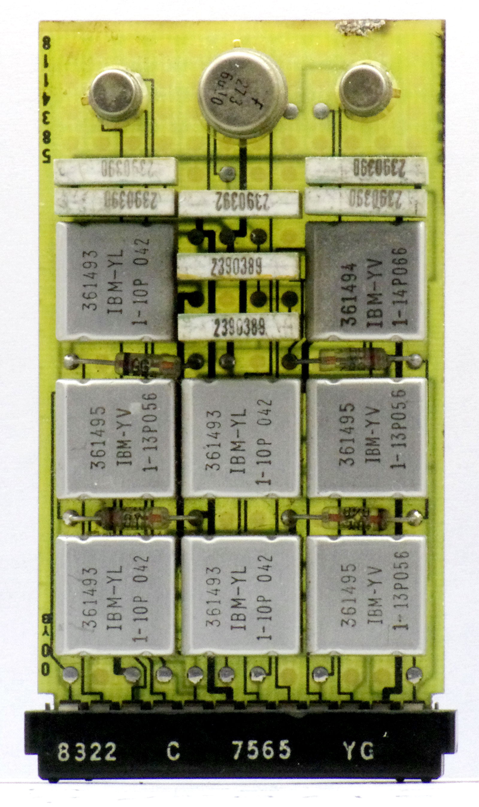
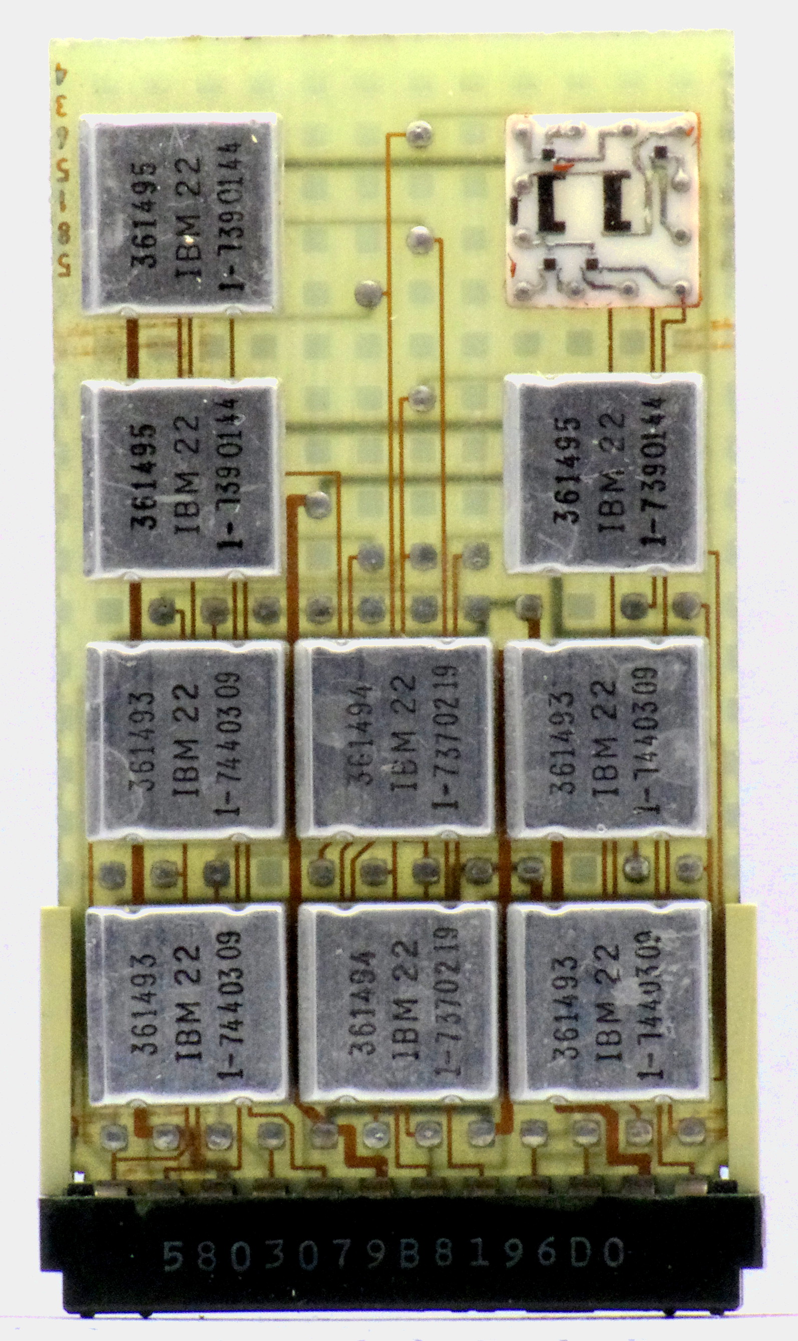
Most of the boards I have consist of three types of logic chips: 361493, 361494 and 361495. In order they are an and-or-inverter, a direct coupled inverter and an and-or extender. This leads me to believe that the cards I have are bus drivers and gates. They are all low-speed, so maybe they are from a peripheral device or smaller model system.
367493circuit361494circuit361495circuit
Schematics of the individual modules, in ascending order.

A look at all the boards I have:
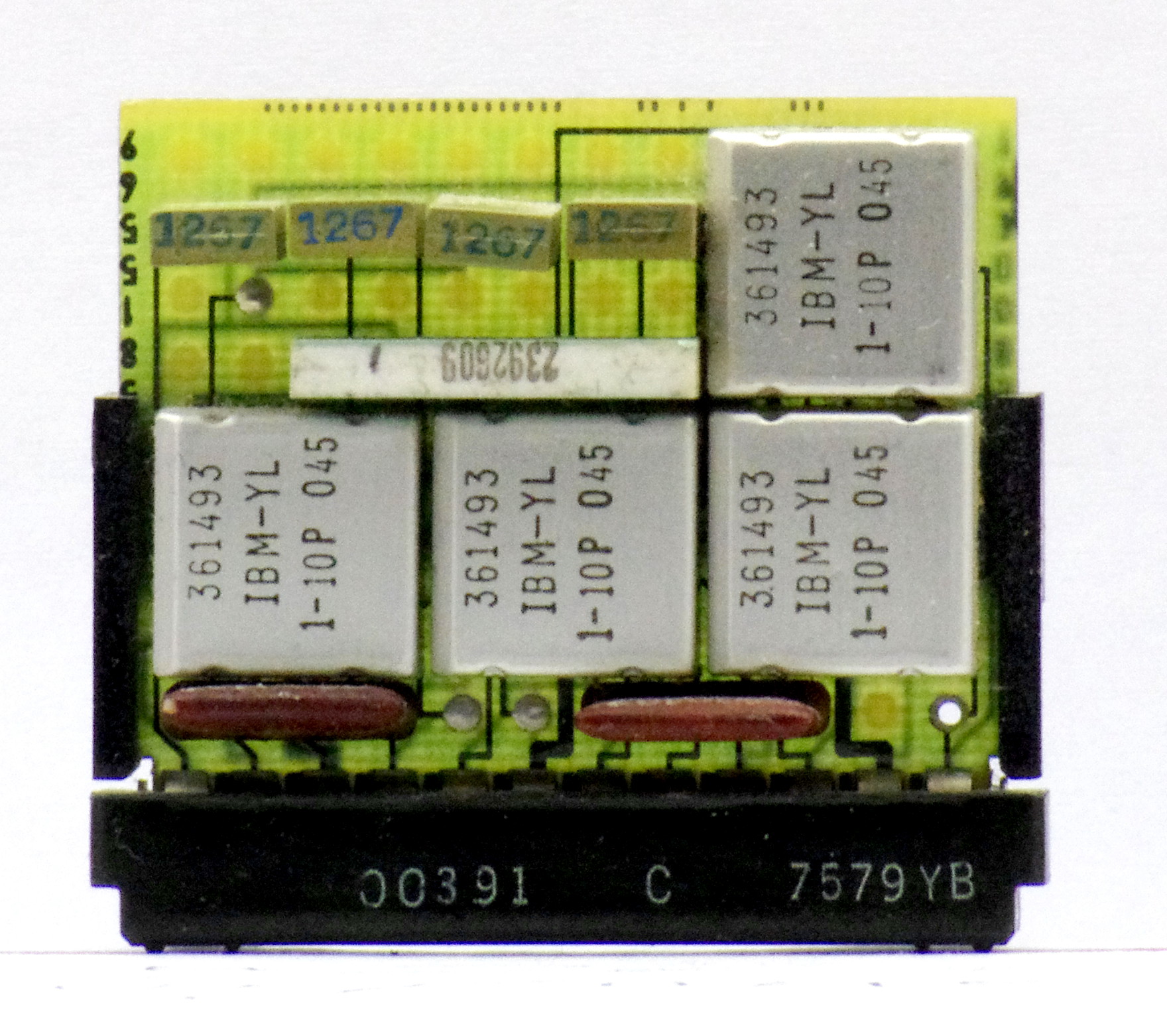
IMGP4193IMGP4191
IMGP4188IMGP4186
IMGP4185IMGP4184
IMGP4183IMGP4181
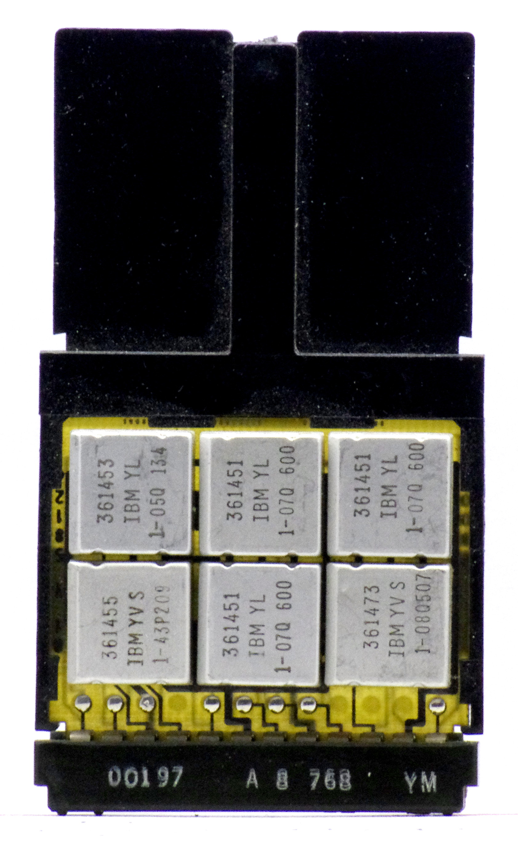
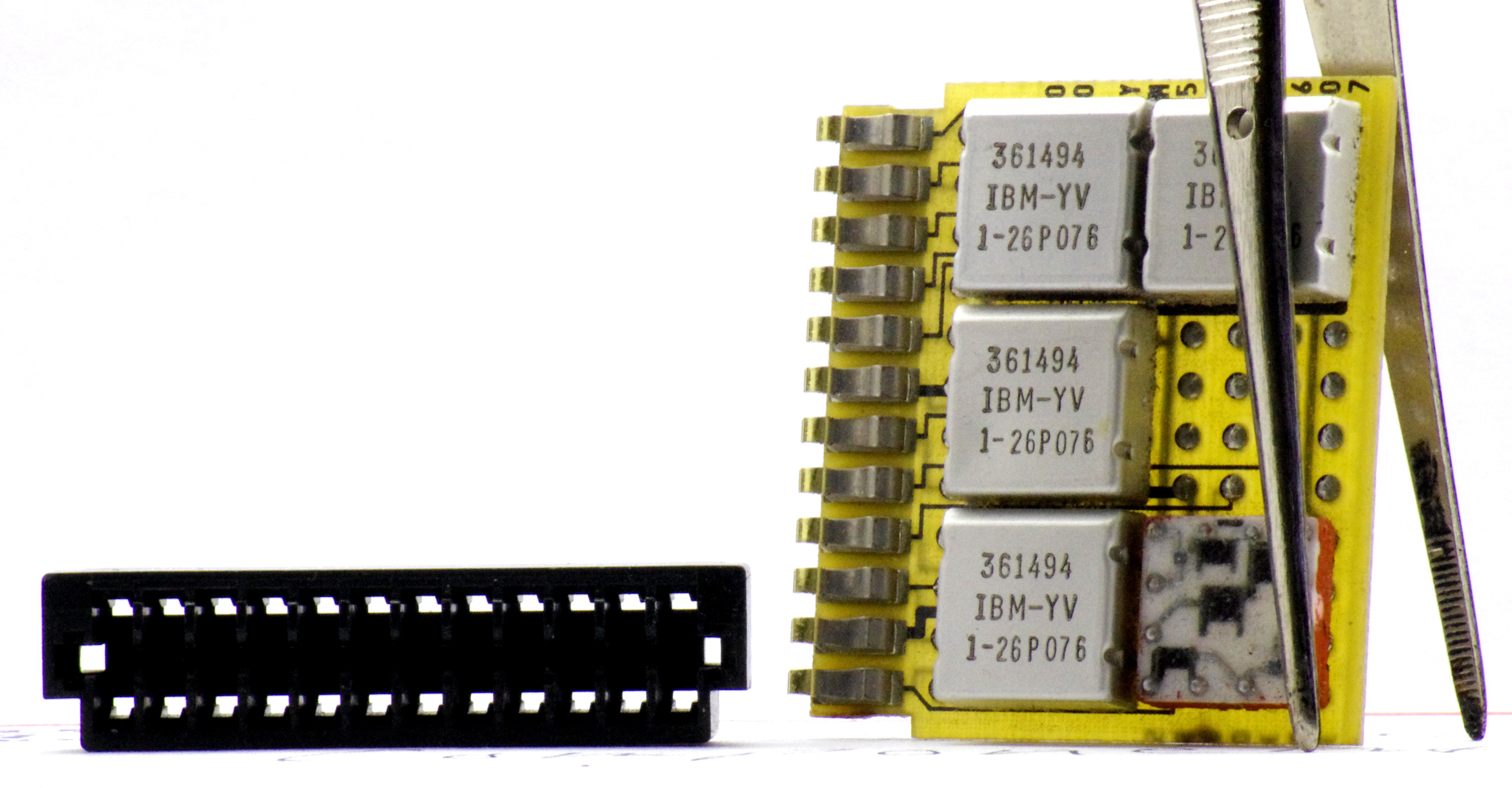
Last, a view of one card, the one pictured at the top with its connector loose. One of the metal tabs that holds the plastic molding on the connector was missing allowing it to slide off relatively easy. I decided this would be a good board to uncap an SLT module on, as it was no longer mint. It gives a good view of some things you can't see from the documentation.
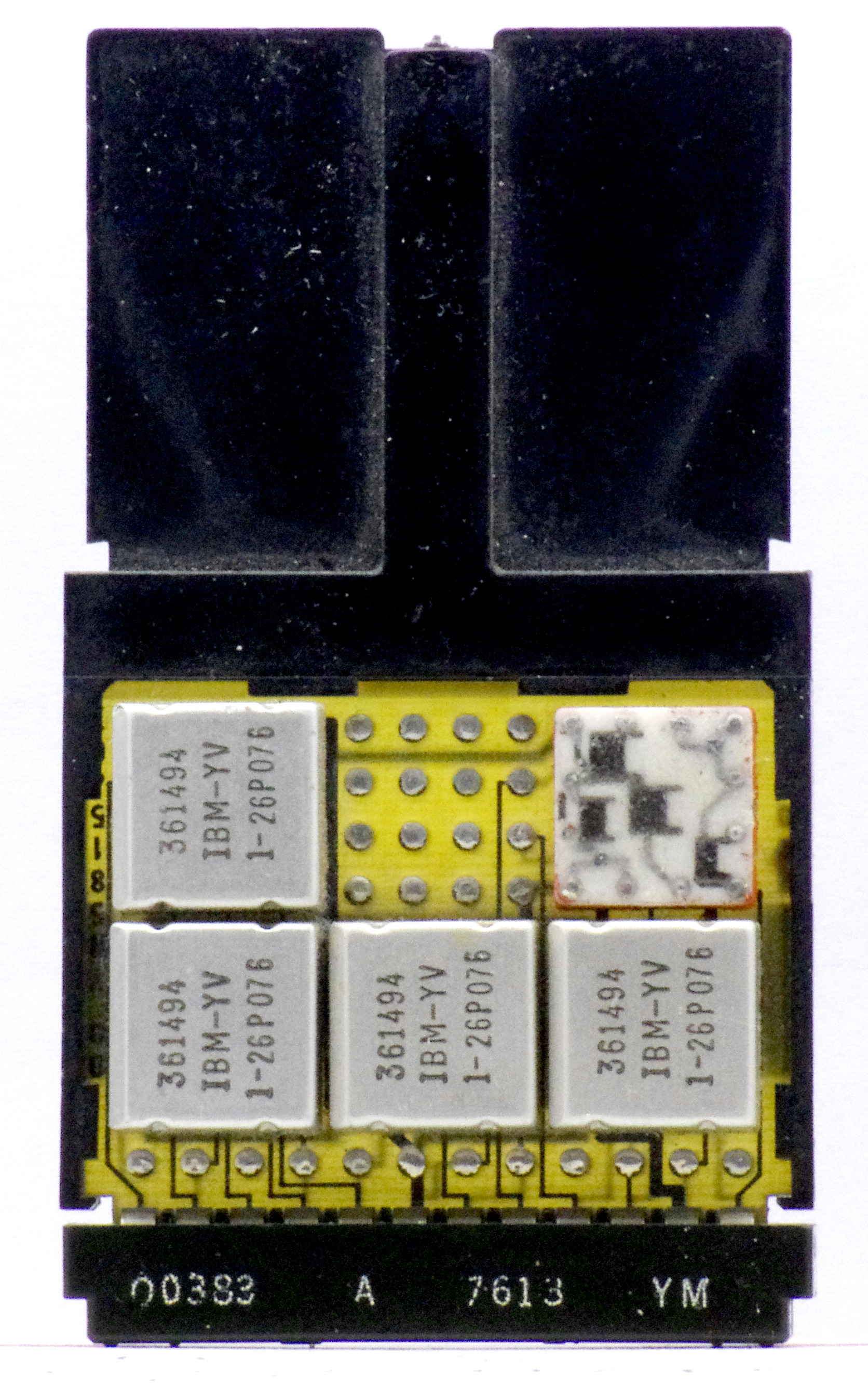
IMGP4182
It is a duplicate of the top right card in the above set of photos.

IMGP4207
With plastic flag and end connector removed, the shape of the board and its traces can be seen better. Silicone gel has been removed from the chip to better display the components.

IMGP4203
A rear view. In both of the above photos it is easy to see that the connector is a part of the board. The plastic connector only serves to guide the pins on the backplane to the pads on the connectors. But just look at all that gold!

The connector seen on these cards had an exceptional lifespan for IBM. Even the 1/8 inch spaced boards and backplane technology did. IBM was installing 4-wide boards in this style as late as the 80s. Although, by then they had been using more standard types of chips, called Monolithic System Technology, or MST. Still packaged in aluminum cans, but with more pins and one little chip of silicon. SLT also got a trip to the moon. Or at least helped get people there. A hardened type of SLT was used int the Launch Vehicle Digital Computer of the Saturn V rocket.

I have learned a lot of this information in a quest to recreate SLT cards. Initially it doesn't seem that hard. The logic can be made using surface-mount components (if you don't mind not having them in fancy little cans). Also, in theory the connector isn't that hard, pins on the board, a receptacle on the card. But it's not a standard pin-header. It's a 1/8 inch spaced connector that is specially molded to fit a particular socket. I have made CAD drawings of an approximation of the plastic molding, but that still leaves contacts to make. I had for a while toyed with making SMS cards because if you also used surface-mount components you would have enough room for capacitors and resistors to get the right response from modern transistors and also never have to drill the board because they're one-sided. But then, you need a 1/8 inch card-edge connector with wire-wrap pins. And they're hard to find...

I consider replicating connectors to be the major limiting factor in reproducing plug-compatible SLT and SMS cards.

Wednesday, April 9, 2014

Happy 50th System/360! Pt.3 Isn't it Fabulous?

tumblr_mk8e4hm1nx1r49q4co1_1280

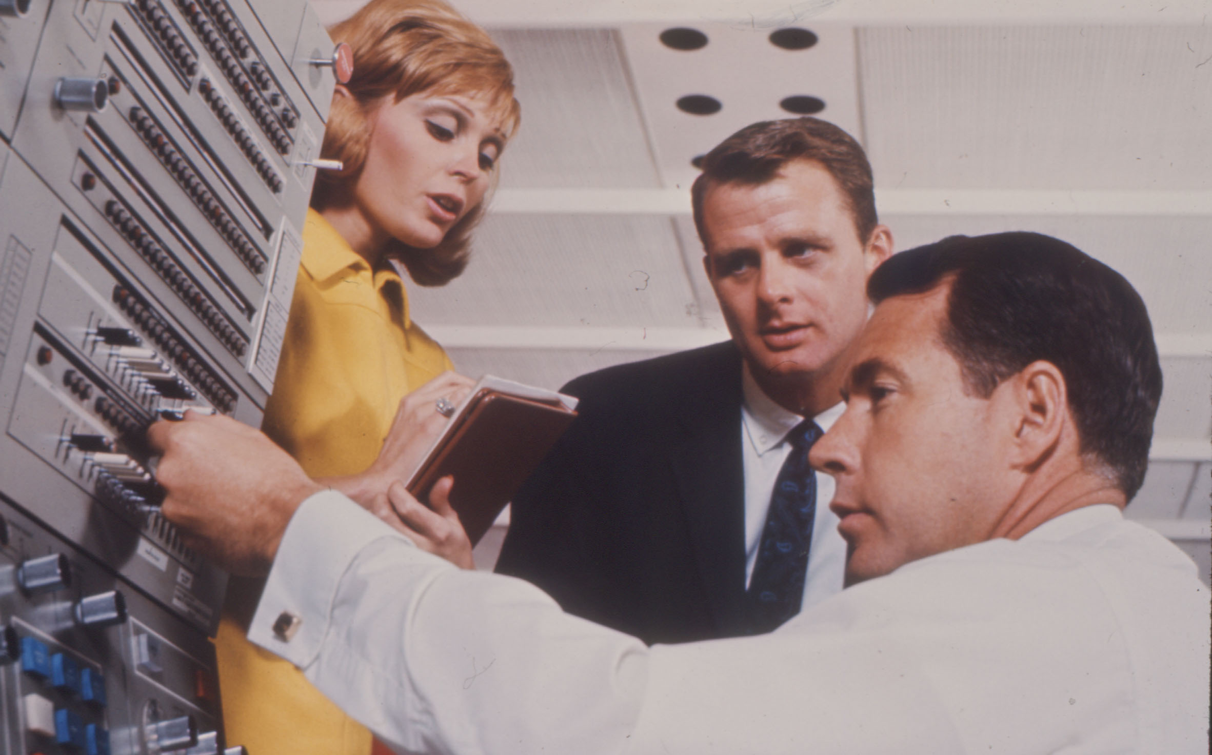
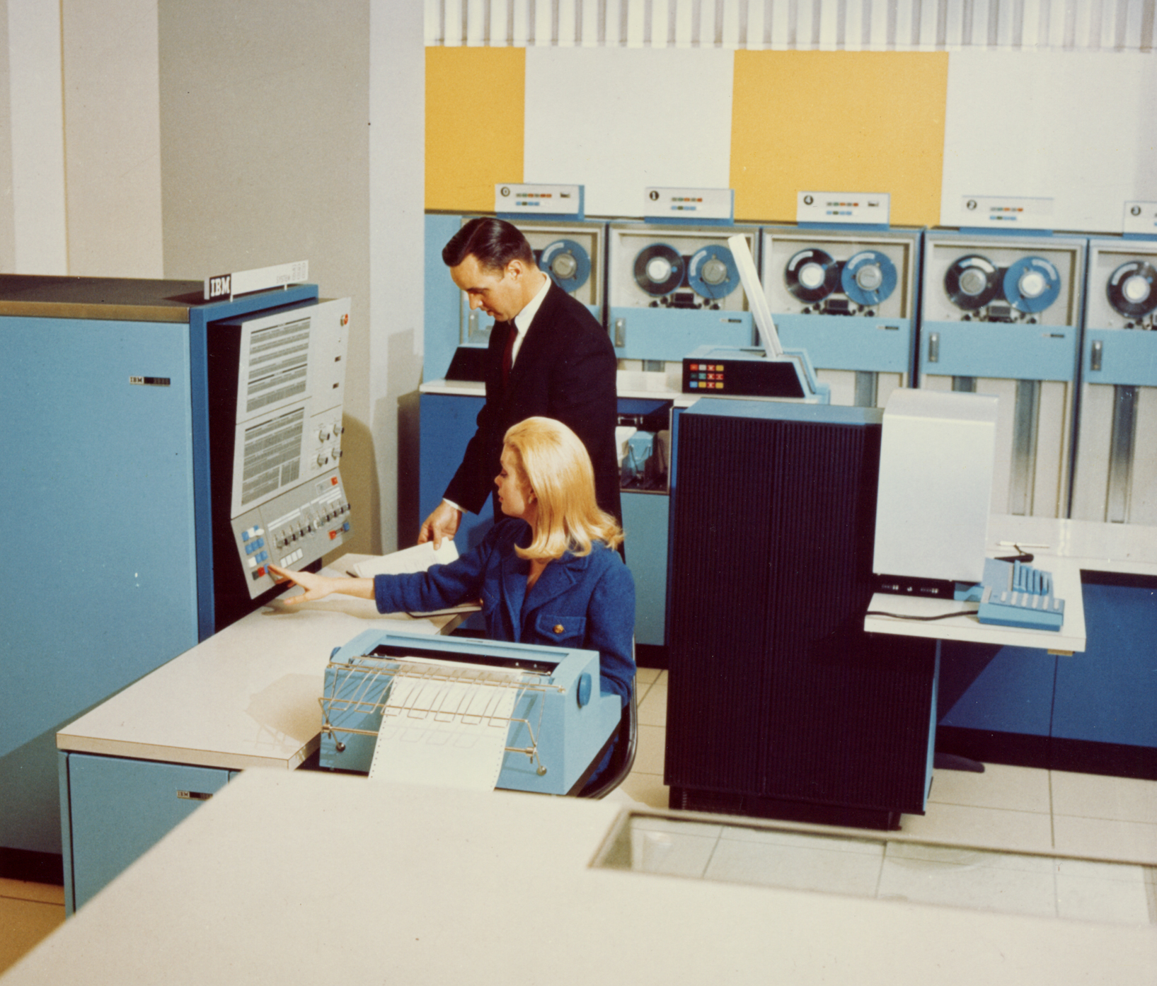
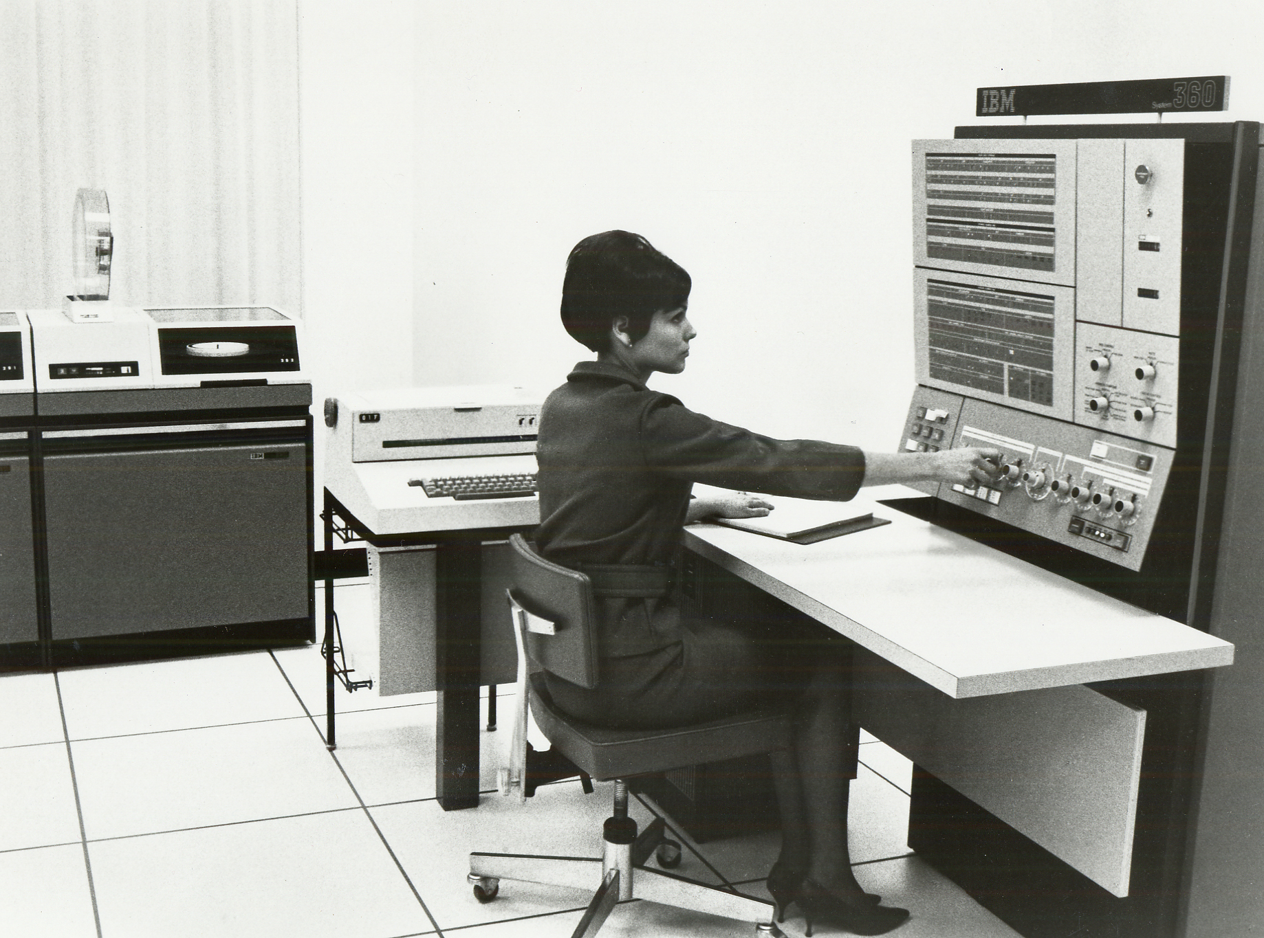
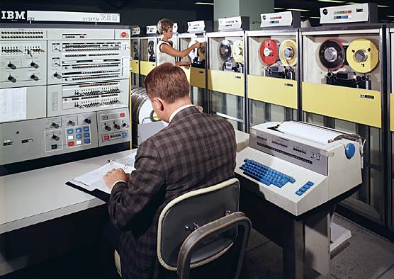
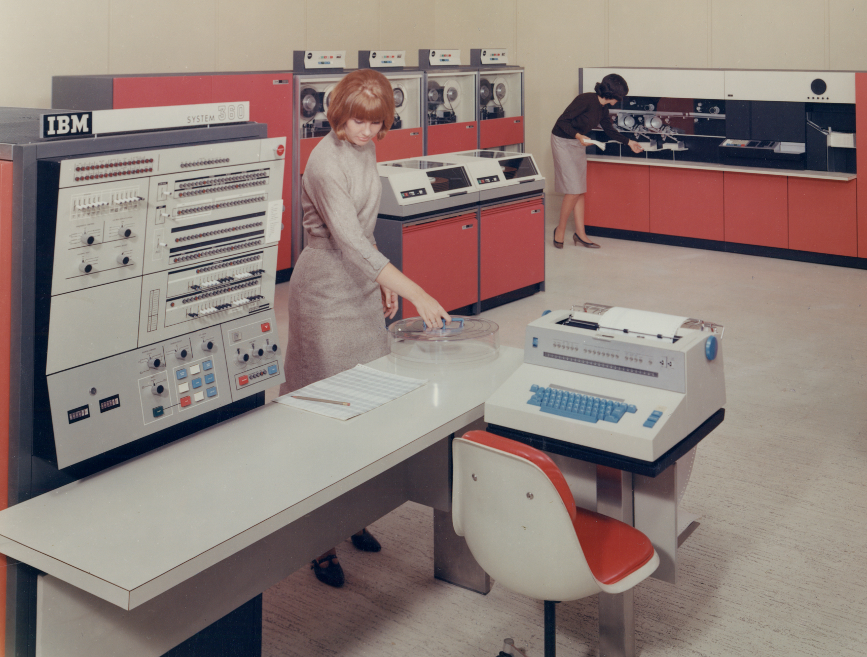
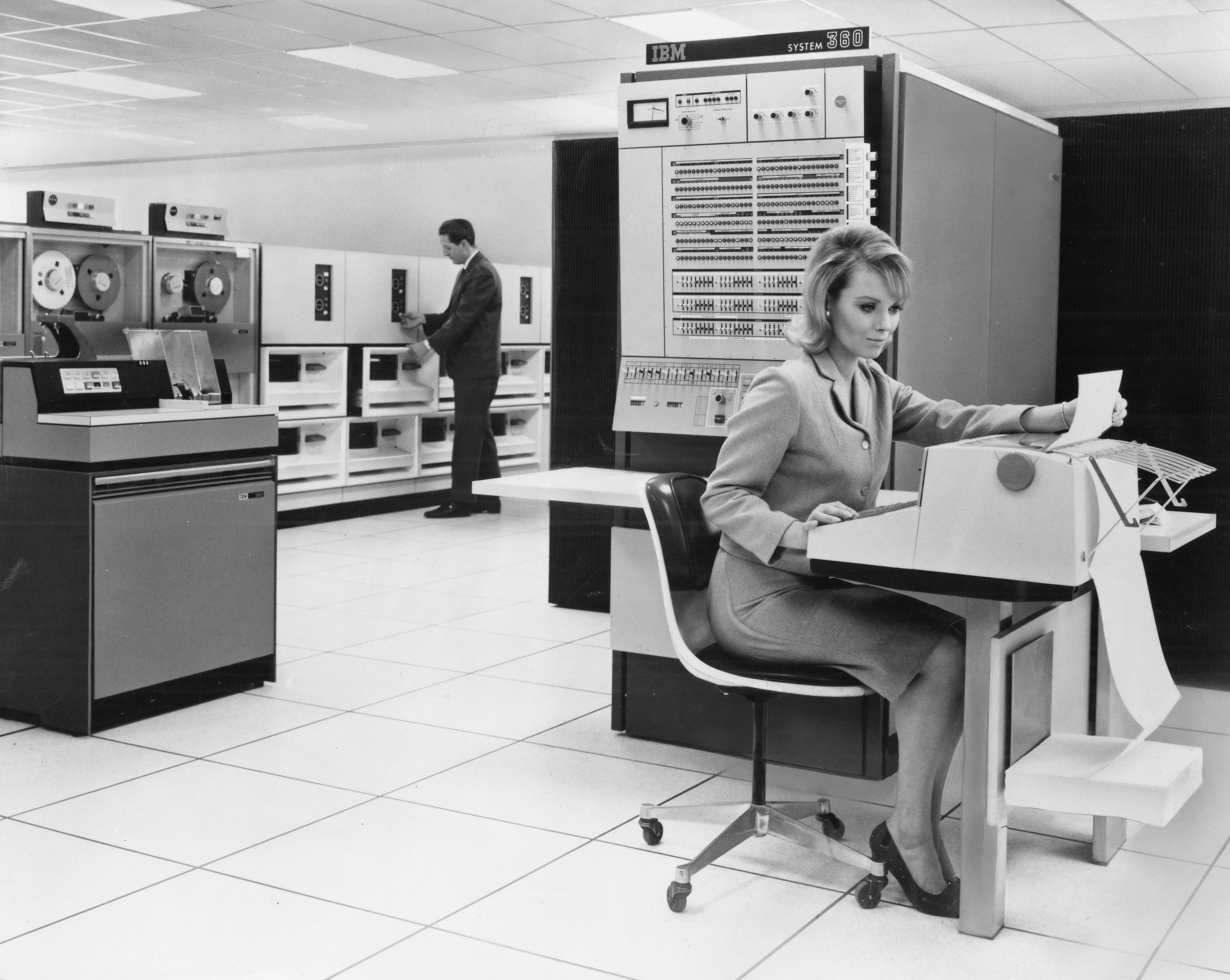
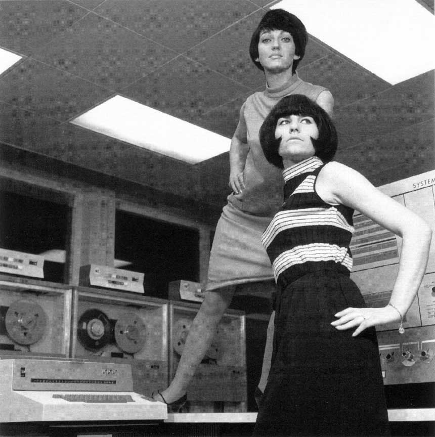
This is a bit of a silly post about all the fabulous "action shots" that were produced with these computers as a primer for a discussion about the design of the 360 series. A lot of these were generated, by IBM and also bored operators. These are some of my favorites.

360mod65a
"I just need a little program, like this high."

ibm360_07

image 55
These three are ready to get things done! (it helps if the computer is on though)

Tuesday, April 8, 2014

Happy 50th, System/360! Pt.2: The Family

ibm360-1
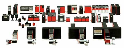
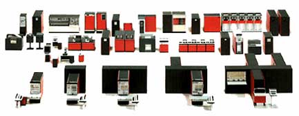
An early promotional photo showing, across the bottom, the then models 30, 40, 50, 60 and 70 processors

For the second part of my anniversary series for the System/360, I want to introduce the members of the computing family; the processors that made up the backbone of the series. In previous years, these would have been completely separate devices or even series, but with System 360 all of these processors had a single unifying theme, or architecture. I'll start off with those that were announced in 1964 and finish with the models that were introduced later.


A quick note about IBM part numbers in this era:
Most every processor at this point had some kind of 4-digit number to designate it, such as 7090, 1401, 1620. Upgrades would be in a similar range; 7094, 1440. And lastly, peripherals would be interspersed according to what line they were offered with; 1403, 1402, 7330. With a whole new series like 360, the "series code" was 2000 and the processors were the base-most elements; model 30=2030 and so on. Other peripherals were given different different prefixes, such as 24XX contained all the tape drives, 25XX was card handling, etc. It was a good way of keeping track of things, but they didn't always stick to it anyway. Just something to keep in mind when reading further.


360genrl_colormod30_Sys360
The Model 30

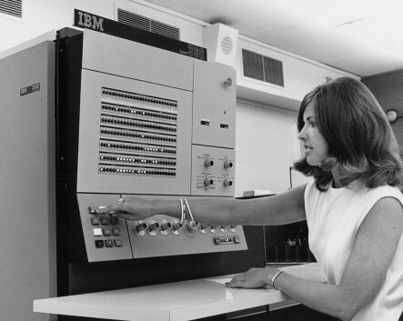
The IBM 2030 in IBM series code, or model 30, was the initial baby of the system. It was the lowest performance machine and looked quite unlike many of the other computers with its bank of knobs for data entry and backlit lucite indicator panel. It is my favorite, partly because of these features. This model was aimed more at the commercial industries for payroll and related tasks. All the computers in the series are 32 bit, but the model 30 has only an 8-bit path to memory, requiring 4 memory cycles to read or write a word to memory. One of the methods that IBM used to keep the lower-cost models cheap was to implement microcode, a read only storage that interprets the instructions to internal signalling, rather than using dedicated circuitry. This was slower, but also cheaper and smaller. The model 30 was the only model to use what was called Card Capacitor Read Only Storage, or CCROS. CCROS was unique because the data contained in it was encoded in Mylar punched cards that had metal patterns printed on them. This allowed the computer to be easily modified if so desired, but was a massive headache to get working. People who switched from an earlier 1401 system often complained that the System/360 was more unreliable than the 1401, most likely due to early issues with this device.


T373925A360genrl2_color
The Model 40

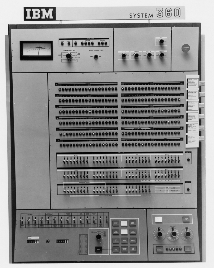
The IBM 2040 was the next step up, with a faster microcode and a wider, 16-bit path to memory, but with an 8-bit arithmetic unit. It was also the first model in the series to use Transformer Read Only Storage, or TROS, for microcode. TROS was similar to "rope" memory in that bits were encoded by whether or not a drive wire passed through a sensing ring. It was faster and more reliable than CCROS. The Model 40 also incorporated some innovations on its front panel that were present on higher-end models. It used individual, front mounted lamps and had a unique way of multiplexing bays of lamps for busses and having the individual bits labelled properly. A knob on the side of the panel would rotate a bank of labels behind a small window that would also operate a switch, changing the readout on the lamps. This model was the most popular, showing up in many universities and businesses.


S360_M50IBMSystem360_Mod50
The Model 50

The IBM 2050 was the first in a series of computers to replace what was considered to be the scientific processing line at IBM, the 7000 series. Unlike the model 30 and 40 it had a 32-bit arithmetic unit and a microcode based on a balanced capacitor store, similar but more reliable than CCROS.


360mod65System_360
The Model 60 (actually the Model 65)

The IBM 2065 was a real workhorse. It used the same microcode as the model 50, but had a 60 bit wide arithmetic unit with an auxiliary 8 bit unit for floating point operations. It also stored its registers in flip flops rather than some variant of core memory, which made it blazing fast (at least comparatively). It also used a different, faster type of main memory.

By this time, the computers are actually getting quite large. The model 30 and 40 pretty much had the same size case (about two refrigerators worth) But as can be seen from the image at the top of the page, the higher models started having compartments jutting out in all directions to house the increasing circuitry (in production the model 40 did not have the rear compartment it has in the image). The cabinets were even taller than those of the first two models. And to think that the computers still needed an additional module or two to talk to peripherals... no wonder people wanted to free up floor space when they were decommissioned.


S360_M75us__en_us__ibm100__apollo__rtcc__800x820
The Model 70 (actually the Model 75)

The IBM 2075 is actually quite an important computer. It was the only computer of the original line-up to not use microcode, but faster hard-wired logic. Other than that factor, it is essentially a beefed-up model 65. What makes this an important computer is that it had a higher addressable memory space and was essentially the supercomputer of the series at the time it was released. But overall, it is important because it was a cluster of five of these computers at NASA's Real Time Computing Center that ran all of the Apollo missions. This is my second favorite computer of the series.


Later Releases

S360_M20_colormodel22S360_1401
Models 20, 22 and 25

These models were later add-ons to the low end to replace unit-record (card processing) equipment. The model 20 was designed in Europe and was not entirely compatible with the larger systems. The models 22 and 25 were small systems that resembled the model 30 and (I think) used TROS for microcode.


S360_M85_ColorS360Mod85_Console
The Model 85

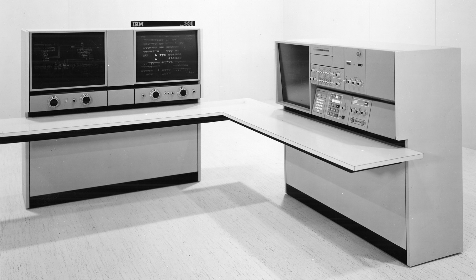
The model 85 was a very unique computer. It did not have a front panel like the other models of the series. Not only was the panel sitting on its own as a desk, but it had a video screen that went along with it. There are very few lights on the front panel, because it was accompanied by a twin microfilm module that provided document reference and also data readout, using the microfilm as a mask and labels. It was hardwired and used a fast thin-film memory for a lower portion of memory. It wasn't very popular and not many were made. It's hard to even find good pictures of it.


The Model 44

The model 44 was essentially a model 40, but with hardwired logic and circuitry for real-time applications. It was intended for scientific purposes but was not very popular.


ibmsuper
Models 91, 95 and 195

These models were the last of the 360 series. They were the highest performance, with special high-speed memories and all hardwired logic. The 95 was a 91 with thin film memory and only two were ever made, both for NASA. The model 195 was almost a System/370 and a model made with 370 circuitry was available as part of that line.

Monday, April 7, 2014

Happy 50th, IBM System/360! Pt.1

us__en_us__ibm100__system_360__360_family_circle__800x638 On this day in 1964, IBM announced what was their largest and most expensive project to date. It was a series that would take over the entire line of current computers. It was called System/360- a name to express its all-encompassing nature.

The idea was simple in its description, but much harder in its implementation. This idea was to create a single series of computers that could handle the needs of business computing, scientific computing and everything else in between, using interchangeable parts and peripherals. If a customer had a low-power system, they could easily upgrade to a larger more powerful system without doing a large amount of reprogramming. The implementation also coincided with new logic hardware (solid logic technology) and a unified style that carried throughout every device.

As one would suspect, this was much harder to implement than to describe. There were reasons why different computers in the IBM line would use different types of logic and different layouts for those devices, not at all least being cost. The System/360 project was a 'bet the business' project for IBM that many engineers and executives at the time were uncomfortable with, but proved to be one of the most significant moves IBM made in the 1960s. The System/360 was involved in many important events in the 1960s, most important being the computer system that landed us on the moon. The system would also be present in countless universities and companies, not to mention the computer of choice for control of air traffic (in some cases still in service until the 1990s!) and the first airline reservation systems.

It has become my favorite computer system since I was quite young and I have been quite disappointed that no one seems to be willing to give this computer a proper 50th. Therefore, I am dedicating this week to the System/360. Every day I will examine a certain aspect of the system in detail, working off of pictures and information that I have amassed over the years.

I have spent more time than I would like to admit researching this system, especially in an effort to create some kind of replication of it on a hardware level. A fools errand perhaps, but when one really wants a computer and most of the actual ones were busted up for scrap, one tends to get a bit desperate. (So far the only major thing holding me back is backplane hardware, which I'll talk about later in the week).

Most of the information that I have been working off of is things that are spaced far throughout the internet. A special shout-out to Bitsavers for being absolutely essential to understanding the hardware of these computers. Also, until recently I did not have regular access to it, but I finally bought the wonderful book by Pugh, Johnson and Palmer, IBM's 360 and Early 370 Systems, that gives just an absolute boatload of information about the formulation, design, architecture and politics of the System/360. If you are interested in this system, it is required reading. It is also a source of information that will show up this week.

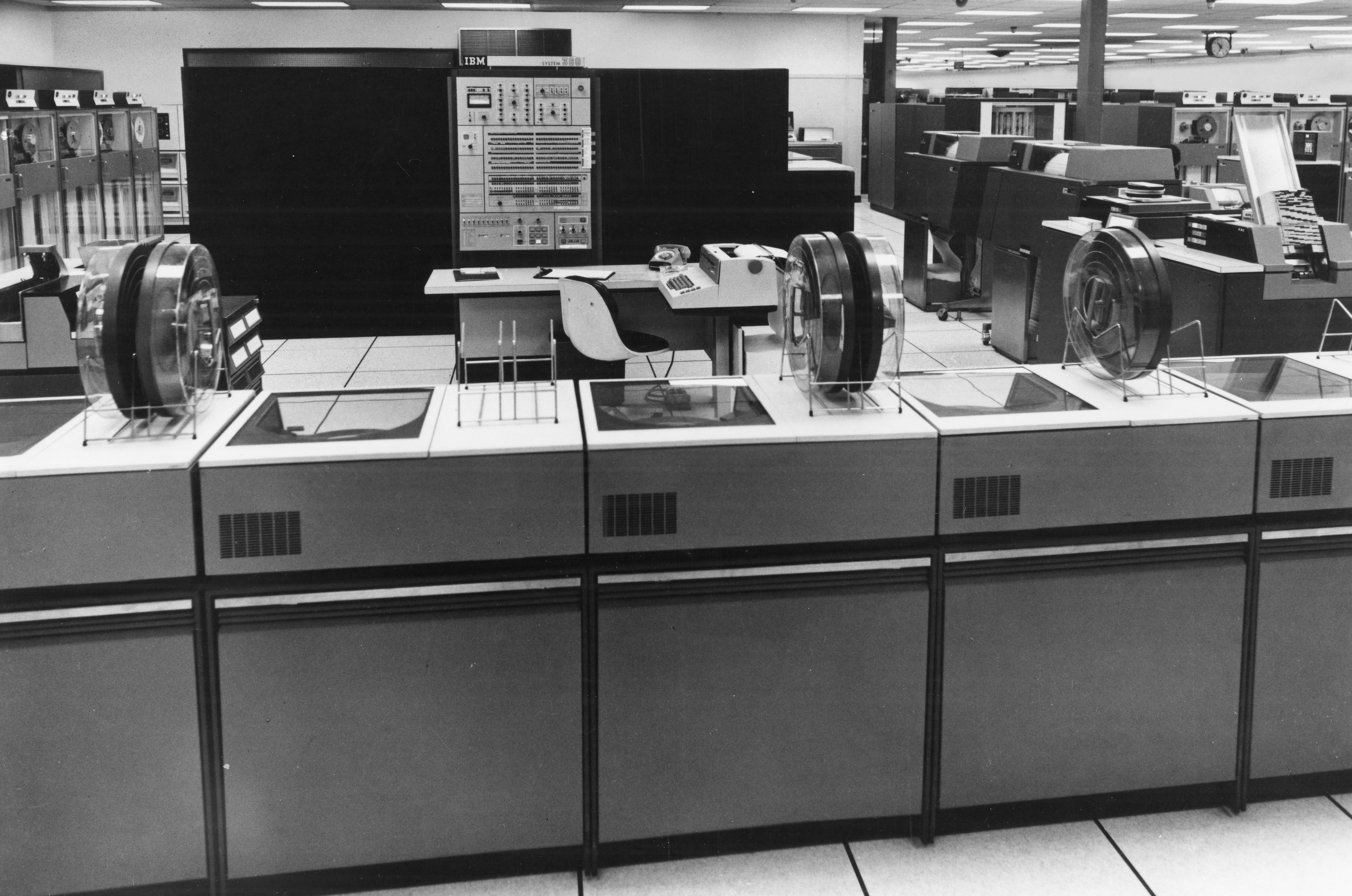
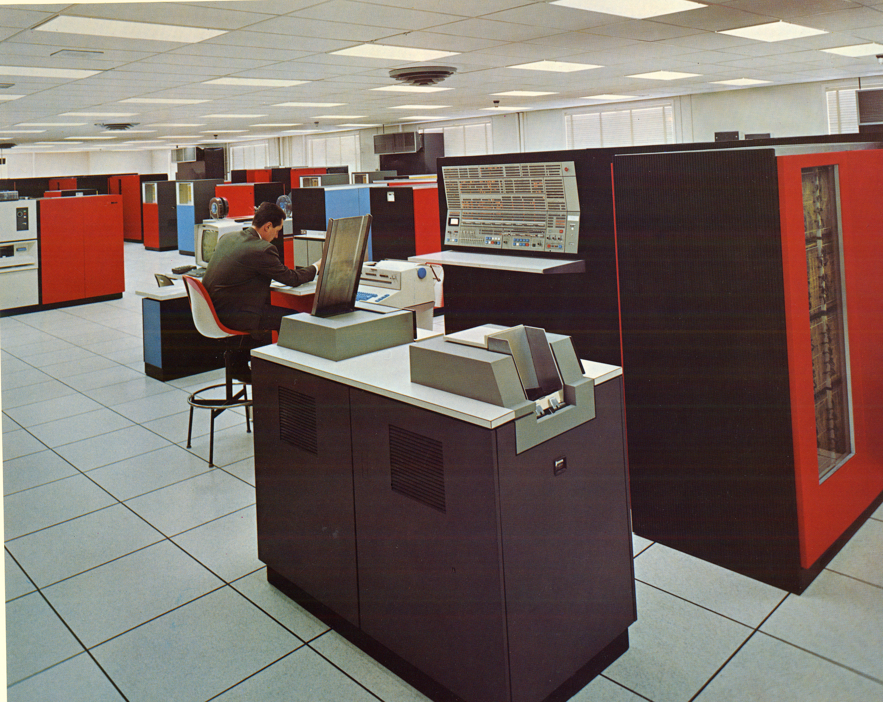
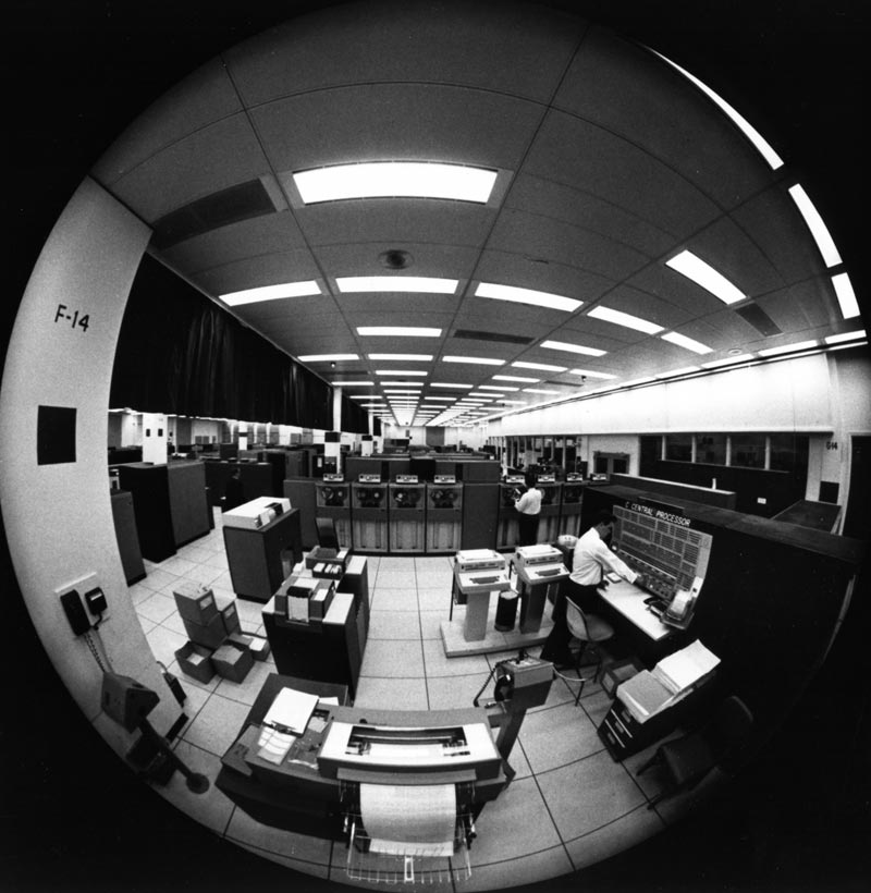
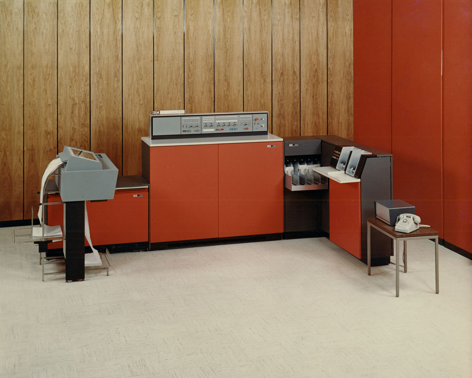
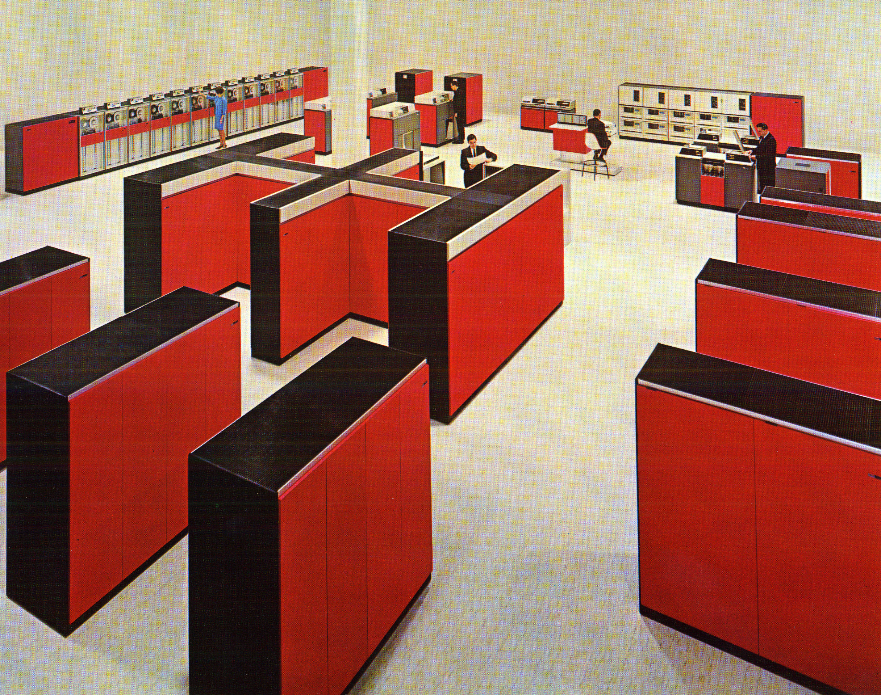
To end this post, and kick off this anniversary week, I will leave you with some of my favorite System/360 pictures.

1964_1_1
Early promotional material

ibm360-1
The System/360 Family

ibm3603
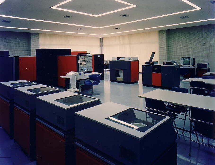
Unknown computer center

Ferrite Cores S360
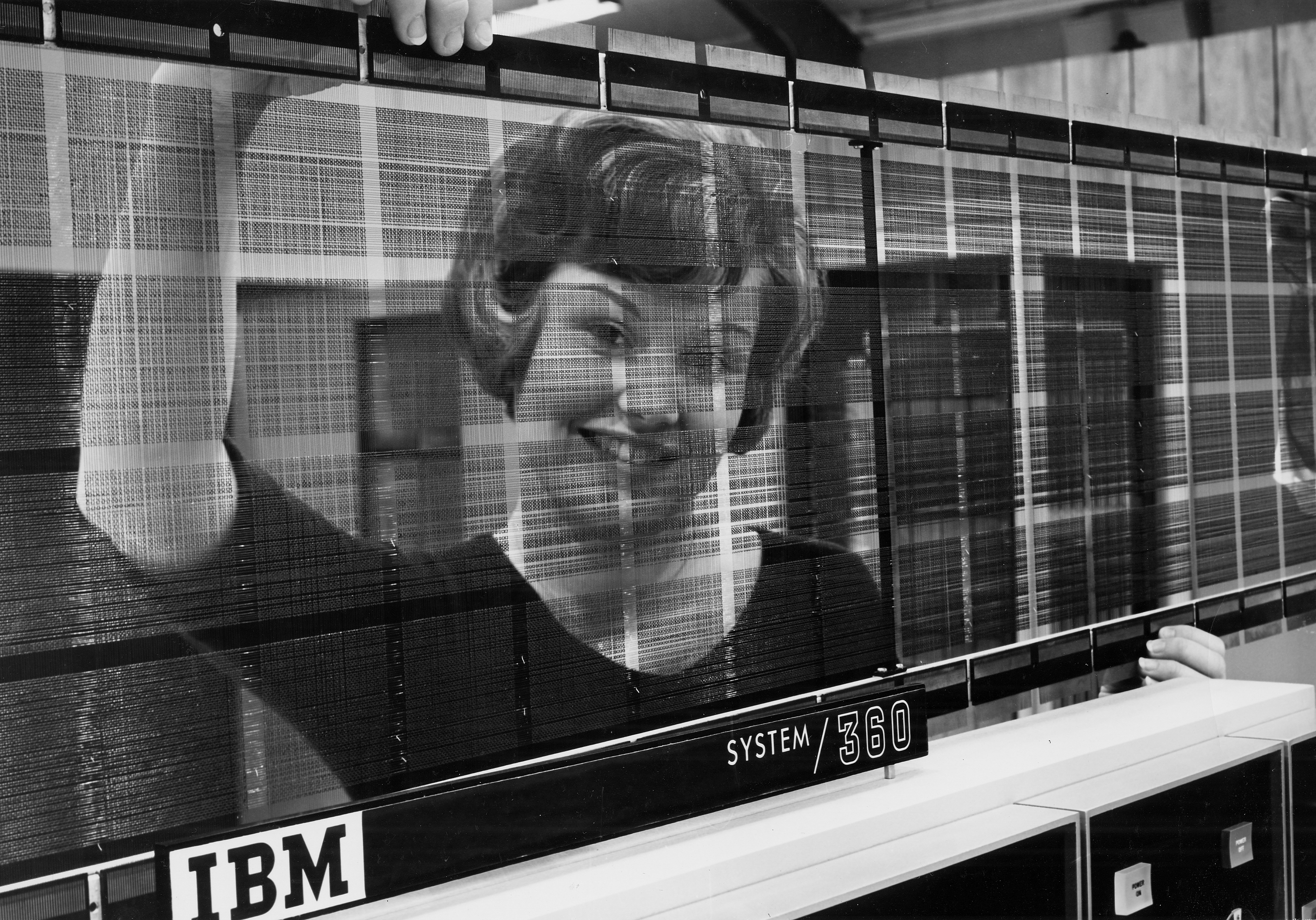
Worker holding up plane of 'Large Core Storage'

MCRwith36075360441969
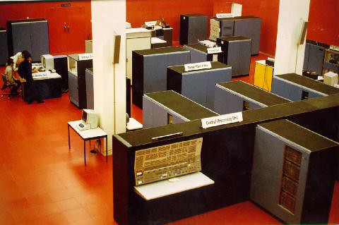
At the University of Waterloo, in the 'Red Room'

us__en_us__ibm100__system_360__watson_at_360__620x350
With IBM CEO Tom Watson Jr.

RTCC
At the NASA Real Time Computing Center(RTCC)